The Bruker SMART CCD detector system is used to collect single crystal or powder diffraction data. Many APS users are familiar with this system from their home laboratories, and it is desireable to be able to use the same software to collect data at the APS using any beamline diffractometer and shutter system. However, the SMART software is written specifically to talk to the Bruker General Goniometer Control System (GGCS) motor/shutter controller. Most beamlines require EPICS control of their diffractometer for use with other software (e.g. SPEC), and will not want to install the GGCS hardware for use only with the SMART software.
The GGCS communicates with the PC running SMART via an RS-232 serial interface. The solution which I have developed is to make an EPICS IOC emulate the GGCS, so that the SMART software thinks it is talking to a GGCS, while it is actually communicating with EPICS.
There are two version of the SMART software: the standard Eulerian geometry version, and the Kappa geometry version. This EPICS software should work with either one, but it has only been tested with Kappa SMART so far. The nomenclature of the SNL program, the database and the medm screen assume the Kappa geometry. If the Eulerian version of SMART is used then one should substitute values for the chi motor wherever the kappa motor is referenced.
SMART can control up to 4 diffractometer axes. These are 2-theta, omega, phi and kappa (or chi). This EPICS software will also work with diffractometers with fewer axes, and we have successfully used it to collect data with a simple system with a single rotation stage, which could be called phi or omega.
The EPICS implementation consists of the following:
smartControl.db. This
database contains almost no “logic” with no
links between records in the database. The records are
simply variables which channel access clients and the
State Notation Language (SNL) program use.smartControl.st. This
program implements all of the logic for emulating the
GGCS, controlling EPICS motors and PVs to control the
shutter and detector trigger.smartControl.adl. This
screen is used to configure and monitor the SNL program.The SMART system and the EPICS IOC must be connected as follows:
The following are the comments from the beginning of smartControl.db
which describe the macro parameters which must be supplied in the
dbLoadRecords command in the vxWorks startup script.
#  This database works with SNL program smartControl.st to allow SMART to
#  control EPICS motors
#
#                   Mark Rivers
#                   September 17, 2000
#
# Macro parameters:
#   $(P)        - PV name prefix
#   $(R)        - PV base record name
#   $(C)        - Card # (0,1,2...) of the board with the IP slot for the
#                 generic serial records
#   $(IPSLOT)   - IP slot (A-D) for the serial I/O module
#   $(CHAN)     - Channel (0-7) for the serial port
#   $(BAUD)     - Baud rate for the serial port
#                 Note: The SMART PC is assumed to be configured with 8 data
#                 bits, 1 stop bit, no parity.
#   $(FSHUT)    - Name of PV to control fast shutter
#   $(SSHUT)    - Name of PV to control slow shutter
#   $(TRIG)     - Name of PV to control detector trigger
$(P) is the prefix for this IOC, for example
13IDC:$(R) is a record base name for this SMART
detector, for example smart1: for the first
SMART detector run through this IOC. $(C),
$(IPSLOT), $(CHAN), $(BAUD)) define the
communications between the SMART PC and the IOC. This
database assumes that the Hideos or MPF server has a name
like a-Serial[0]. If another naming
convention is used then the database will need to be
modified.$(FSHUT) must be the name of an EPICS PV
which closes the fast x-ray shutter when it has the value
1, and opens the shutter when it has the value 0. $(SSHUT) is a similar PV for a slow shutter,
for example a shutter on an x-ray generator. Such
hardware of often not used on a beamline, but the PV must
exist. One should use a soft binary output record or an
unused output of a digital I/O board if there is no slow
shutter hardware. $(TRIG) is the name of an EPICS PV which
controls the TTL trigger input on the CCD controller. It
has the value 0 to turn the detector on, and 1 to turn it
off.The following is an example of the lines which must be put in
the vxWorks startup file to load smartControl.db.
Note that the command line is longer than the vxWorks limit, so
the command must be built using malloc, strcpy
and strcat.
# SMART detector database
str=malloc(256)
strcpy(str,"P=13IDC:,R=smart1,C=0,IPSLOT=a,CHAN=6,BAUD=9600,")
strcat(str,"FSHUT=UnidigBo0,TRIG=UnidigBo1,SSHUT=UnidigBo2")
dbLoadRecords("CARSApp/Db/smartControl.db",str)
After iocInit is called in the startup script the
SNL program must be started. Here is an example:
seq &smartControl, "P=13IDC:,R=smart1,TTH=m29,OMEGA=m27,PHI=m25,KAPPA=m26,SCALER=scaler1,I0=2,stack=10000"
In this command P and R are the same
as that used in loading the database.
TTH, OMEGA, PHI and KAPPA are the
names of the EPICS motors controlling these axes. These motors
are assumed to be in the same IOC that is running the SNL
program, and to be named $(P)mN, for example 13IDC:m29.
SCALER is the name of an EPICS scaler record
which should be used to obtain normalization information for each
frame. I0 is the number of the scaler channel (1, 2,
...) which contains that normalization information. Ideally this
should be an ion chamber mounted downstream of the shutter, so
that it records the integrated beam intensity seen by the sample
during each frame. This information is passed to SMART and is
written in the data files for normalization by SAINT. The scaler
is assumed to be in the same IOC that is running the SNL program,
and to be named $(P)$(SCALER), for example 13IDC:scaler1.
If an Eulerian geometry is being used then set KAPPA
to the name of the EPICS motor controlling chi. If the
diffractometer contains fewer than 4 axes, then set the unused
axes to the same EPICS motor as one of the axes which is used.
The MEDM screen will be used to tell the SNL program not to move
axes which don't exist. For example, if the diffractometer
contains a single axis, phi, which is motor m29 then
the command might look like.
smartControl,P=13IDC:,R=smart1,TTH=m29,OMEGA=m29,PHI=m29,KAPPA=m29,SCALER=scaler1,I0=2,stack=10000"
The source files for smartControl are available in the
ccd application.
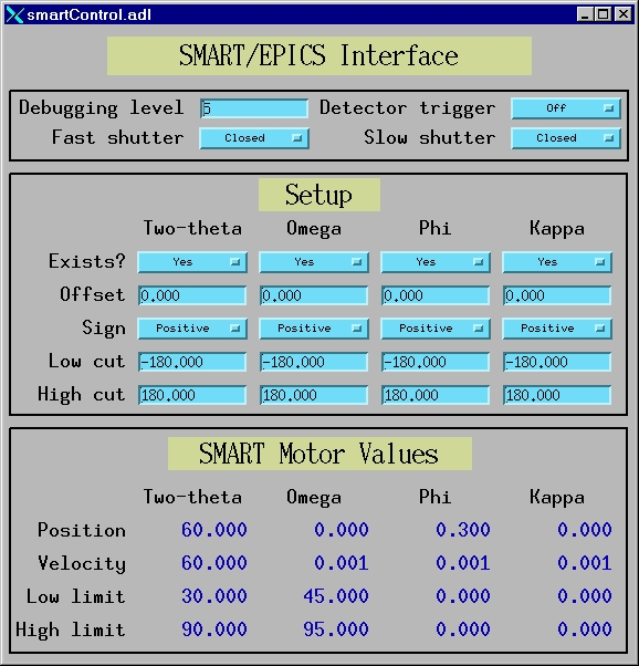
The following shows the MEDM screen (smartControl.adl)
with which the user can view and modify the smartControl
database parameters. smartControl.adl is called with
macro parameters P and R. These are the
prefix and record base used when the database was loaded.
Debugging level is used to control debugging
print statements to the vxWorks console port. The values range
from 0 (no output), 1 (errors and warnings only) through 5
(maximum amount of debugging output). This output can be useful
for seeing what commands are being received from SMART, and the
responses being sent back to SMART. Note, however, that debugging
output reduces the performance of smartControl and
so Debugging level should normally be set to 0.
Detector trigger, Fast shutter and Slow
shutter are used to monitor the state of these control
signals, and also to change them manually if desired.
Under the Setup menu are 5 controls for each
motor.
Exists is a flag which is used to signal
whether or not a given axis actually exists. If an axis
does not exist then smartControl will not
attempt to communicate with that EPICS motor.Offset and Sign are used to
convert from the EPICS motor coordinate system to the
SMART coordinate system. The equation relating the two is
EPICS = Offset + Sign*SMART. If the
coordinate systems are the same then Offset
should be 0 and Sign should be Positive
(1). If the sign convention is different for EPICS and
SMART then Sign should be Negative
(-1).High cut and Low cut are used
to determine when the axis should "roll-over"
by 360 degrees. The relationship, in EPICS motor
coordinates, is:High
cut then the target position is
decremented by 360 degrees. Low cut
then the target position is incremented by 360
degrees.Under the SMART Motor Values screen are 4 values for each motor.
Position is the last position which SMART
commanded this motor to move to. If the motor has never
been told to move by SMART then this value will be 0.Velocity is the last velocity command which
SMART issued for this motor. If the motor has never been
sent a velocity command then this value will be 0.Low limit and High limit are
the last limit values which SMART issued for this motor.The EPICS motor record specifies an acceleration time in
seconds rather than a true acceleration value, for example in
deg/sec/sec. Using a constant acceleration time is not ideal for
oscillation diffraction measurements, since it can lead to
excessively long acceleration times when the oscillation speed is
small. For example, on our Newport diffractometer the phi axis
has a maximum speed of 4 deg/sec, and a maximum acceleration
value of 16 deg/sec/sec. This means that we program the EPICS
motor .VELO field to 4 deg/sec and the .ACCL
field to 0.25 seconds. However, for an oscillation frame in SMART
we might use a 0.2 degree oscillation and 2 second exposure, for
a speed of 0.1 deg/sec. If the acceleration time is unchanged
then the motor will spend 0.5 seconds accelerating and
decelerating, which is 25% of the total exposure time.
Reflections which are in the Bragg condition during these times
will appear too intense. However, it is not necessary to have
such long acceleration times for a 0.1 deg/sec move. Since the
motor can accelerate at 16 deg/sec/sec, the acceleration time can
be reduced to 0.007 seconds.
To minimize the time spent accelerating and decelerating smartControl
does the following:
.VELO
field for each motor is set to the maximum slew speed in
deg/sec, and the .ACCL field is set to the
minimum acceleration time for that slew speed. It
computes the maximum acceleration in deg/sec/sec.
Whenever a motor is moved by SMART the acceleration time
is recomputed using the current velocity to maintain a
constant true acceleration in deg/sec/sec. This leads to
both faster data collection and more accurate
intensities.With the Newport diffractometer and the MM4005 motor
controller there is a global variable drvMM4000ReadbackDelay
which controls the time between when the MM4005 reports that the
motor has stopped moving and when the driver reads the final
position of the motor. This delay is a temporary fix to allow for
the settling times of the DC motors. When using EPICS to
step-scan, for example with SPEC, this value must be set to the
worst-case settling time of any axis. We use a value of 0.5
seconds on our diffractometer. However, when using the
diffractometer with SMART and collecting oscillation data with
the phi axis drvMM4000ReadbackDelay should be set to
0.0. If it is left at 0.5 seconds then each frame will be
collected for an additional 0.5 seconds at the final motor
position, which will clearly lead to incorrect intensities if
there are reflections in the Bragg condition at this point. The
phi axis does not have an on-axis encoder and has a very fast
settling time, so the delay is not necessary.
smartControl does not attempt a complete
emulation of the GGCS. The reason for this is that the GGCS
syntax is very arcane and difficult to parse, and SMART actually
only uses a small subset of the GGCS command set. What has been
done is to emulate all of the GGCS commands that the current
release of SMART actually uses. This leads to a potential problem
when new versions of SMART are released, since they may use
additional GGCS commands. smartControl will need to
be modified to emulate additional GGCS commands if this occurs.
smartControl is limited in the accuracy of the
exposure timing by latencies in EPICS channel access, in the
motor driver and communication, and in the shutter operation. For
each frame the SNL program does the following in response to a
single command line from SMART:
This approach works well if the exposure times are long
compared to the shutter opening time and the latencies between
steps 4-8 above. On APS undulator beamlines exposure times of
less than 1 second are feasible, and the latencies could be a
significant fraction of the exposure time. In general the EPICS
software latencies are very small, because although the SNL
program uses Channel Access, all of the PVs are actually in the
same IOC as the SNL program. The performance of smartControl
is probably very similar to an actual GGCS system, although no
measurements have been made yet to establish the latencies.
In the future smartControl will be enhanced to
use the trajectory scanning and synchronization features of the
MM4005 and OMS-58 motor controllers to improve the accuracy of
the exposure timing. This software will ensure that motor is
actually at the correct speed and position at the instant the
shutter opens and closes. This will require controller-specific
software and hardware.