simDetector.adl
This is an EPICS areaDetector driver for a simulated area detector. The simulation detector is useful as a model for writing real detector drivers. It is also very useful for testing plugins and channel access clients.
This driver inherits from ADDriver. It implements nearly all of the parameters in asynNDArrayDriver.h and in ADArrayDriver.h, with the exception of the file saving parameters, which it does not implement. It also implements a few parameters that are specific to the simulation detector. The simDetector class documentation describes this class in detail.
The writeInt32 and writeFloat64 methods override those in the base class. The driver takes action when new parameters are passed via those interfaces. For example, the ADAcquire parameter (on the asynInt32 interface) is used to turn acquisition (i.e. computing new images) on and off.
The simulation driver-specific parameters are the following:
| Parameter Definitions in simDetector.cpp and EPICS Record Definitions in simDetector.template | ||||||
| Parameter index variable | asyn interface | Access | Description | drvInfo string | EPICS record name | EPICS record type |
|---|---|---|---|---|---|---|
| SimGainX | asynFloat64 | r/w | Gain in the X direction | SIM_GAINX |
$(P)$(R)GainX $(P)$(R)GainX_RBV |
ao ai |
| SimGainY | asynFloat64 | r/w | Gain in the Y direction | SIM_GAINY |
$(P)$(R)GainY $(P)$(R)GainY_RBV |
ao ai |
| SimGainRed | asynFloat64 | r/w | Gain of the red channel | SIM_GAIN_RED |
$(P)$(R)GainRed $(P)$(R)GainRed_RBV |
ao ai |
| SimGainGreen | asynFloat64 | r/w | Gain of the green channel | SIM_GAIN_GREEN |
$(P)$(R)GainGreen $(P)$(R)GainGreen_RBV |
ao ai |
| SimGainBlue | asynFloat64 | r/w | Gain of the blue channel | SIM_GAIN_BLUE |
$(P)$(R)GainBlue $(P)$(R)GainBlue_RBV |
ao ai |
| SimResetImage | asynInt32 | r/w | Set to 1 to reset image back to initial conditions | RESET_IMAGE |
$(P)$(R)Reset $(P)$(R)Reset_RBV |
longout longin |
| SimMode | asynInt32 | r/w |
Sets the simulation mode. Options are:
|
SIM_MODE |
$(P)$(R)SimMode $(P)$(R)SimMode_RBV |
mbbo mbbi |
| Parameters for Array of Peaks Mode | ||||||
| SimPeaksStartX | asynInt32 | r/w | X location of the first peak centroid | SIM_PEAK_START_X |
$(P)$(R)PeakStartX $(P)$(R)PeakStartX_RBV |
longout longin |
| SimPeaksStartY | asynInt32 | r/w | Y location of the first peak centroid | SIM_PEAK_START_Y |
$(P)$(R)PeakStartY $(P)$(R)PeakStartY_RBV |
longout longin |
| SimPeaksWidthX | asynInt32 | r/w | X width of the peaks | SIM_PEAK_WIDTH_X |
$(P)$(R)PeakWidthX $(P)$(R)PeakWidthX_RBV |
longout longin |
| SimPeaksWidthY | asynInt32 | r/w | Y width of the peaks | SIM_PEAK_WIDTH_Y |
$(P)$(R)PeakWidthY $(P)$(R)PeakWidthY_RBV |
longout longin |
| SimPeaksNumX | asynInt32 | r/w | Number of peaks in X direction | SIM_PEAK_NUM_X |
$(P)$(R)PeakNumX $(P)$(R)PeakNumX_RBV |
longout longin |
| SimPeaksNumY | asynInt32 | r/w | Number of peaks in Y direction | SIM_PEAK_NUM_Y |
$(P)$(R)PeakNumY $(P)$(R)PeakNumY_RBV |
longout longin |
| SimPeaksStepX | asynInt32 | r/w | X step between peaks | SIM_PEAK_STEP_X |
$(P)$(R)PeakStepX $(P)$(R)PeakStepX_RBV |
longout longin |
| SimPeaksStepY | asynInt32 | r/w | Y step between peaks | SIM_PEAK_STEP_Y |
$(P)$(R)PeakStepY $(P)$(R)PeakStepY_RBV |
longout longin |
| SimPeakHeightVariation | asynInt32 | r/w |
Used to introduce randomness in the peak height. If non-zero then each gaussian
peak in the array is assigned a scaling factor. scalingFactor = 1.0 + (rand()%peakVariation +1)/100.0 |
SIM_PEAK_HEIGHT_VARIATION |
$(P)$(R)PeakVariation $(P)$(R)PeakVariation_RBV |
longout longin |
| SimNoise | asynInt32 | r/w |
Used to introduce randomness. If non-zero then each affected pixel is assigned a
scaling factor. scalingFactor = 1.0 + (rand()%noise +1)/100.0 |
SIM_NOISE |
$(P)$(R)Noise $(P)$(R)Noise_RBV |
longout longin |
| Parameters for Sine Mode | ||||||
| SimSinOffset | asynFloat64 | r/w | The offset value added to the image. | SIM_SIN_OFFSET |
$(P)$(R)SineOffset $(P)$(R)SineOffset_RBV |
ao ai |
| SimSinNoise | asynFloat64 | r/w | The amount of random noise added to the image. | SIM_SIN_NOISE |
$(P)$(R)SineNoise $(P)$(R)SineNoise_RBV |
ao ai |
| SimXSinOperation | asynInt32 | r/w |
The operation to use to combine XSine1 and XSine2. Choices are:
0: Add 1: Multiply |
SIM_XSIN_OPERATION |
$(P)$(R)XSineOperation $(P)$(R)XSineOperation_RBV |
mbbo mbbi |
| SimYSinOperation | asynInt32 | r/w |
The operation to use to combine YSine1 and YSine2. Choices are:
0: Add 1: Multiply |
SIM_YSIN_OPERATION |
$(P)$(R)YSineOperation $(P)$(R)YSineOperation_RBV |
mbbo mbbi |
| Sim[X,Y]Sin[1,2]Ampliude | asynFloat64 | r/w | The amplitude of the sine wave. There is a record for each of the 4 sine waves: XSine1, XSine2, YSine1, YSine2. | SIM_[X,Y]SIN[1,2]_AMPLITUDE |
$(P)$(R)[X,Y]Sine[1,2]Amplitude $(P)$(R)[X,Y]Sine[1,2]Amplitude_RBV |
ao ai |
| Sim[X,Y]Sin[1,2]Frequency | asynFloat64 | r/w | The frequency of the sine wave. A frequency of 1 means there is one complete period of the sine wave across the image in the X or Y direction. There is a record for each of the 4 sine waves: XSine1, XSine2, YSine1, YSine2. | SIM_[X,Y]SIN[1,2]_FREQUENCY |
$(P)$(R)[X,Y]Sine[1,2]Frequency $(P)$(R)[X,Y]Sine[1,2]Frequency_RBV |
ao ai |
| Sim[X,Y]Sin[1,2]Phase | asynFloat64 | r/w | The phase of the sine wave in degrees. A phase of 90 is the same as a cosine wave. There is a record for each of the 4 sine waves: XSine1, XSine2, YSine1, YSine2. | SIM_[X,Y]SIN[1,2]_PHASE |
$(P)$(R)[X,Y]Sine[1,2]Phase $(P)$(R)[X,Y]Sine[1,2]Phase_RBV |
ao ai |
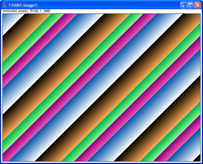
For monochrome images (NDColorMode=NDColorModeMono) the simulation driver initially sets the image[i, j] = i*SimGainX + j*SimGainY * ADGain * ADAcquireTime * 1000. Thus the image is a linear ramp in the X and Y directions, with the gains in each direction being detector-specific parameters. Each subsquent acquisition increments each pixel value by ADgain*ADAcquireTime*1000. Thus if ADGain=1 and ADAcquireTime=.001 second then the pixels are incremented by 1. If the array is an unsigned 8 or 16 bit integer then the pixels will overflow and wrap around to 0 after some period of time. This gives the appearance of bands that appear to move with time. The slope of the bands and their periodicity can be adjusted by changing the gains and acquire times.
For color images (NDColorMode=NDColorModeRGB1, RGB2 or RGB3) there are 3 images computed, one each for the red, green and blue channels. Each image is computed with the same algorithm as for the monochrome case, except each is multiplied by its appropriate gain factor (SimGainRed, SimGainGreen, SimGainBlue). Thus if each of these color gains is 1.0 the color image will be identical to the monochrome image, but if the color gains are different from each other then image will have color bands.
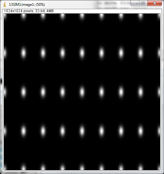
For monochrome images, an array of gaussian peaks is produced. The user specifies the start location for the first peak in PeakStartX & PeakStartY. The size of the peak is controlled by PeakWidthX and PeakWidthY. The array is specified by giving the number of peaks in each direction with PeakNumX and PeakNumY and the step size between peak centroids with PeakStepX and PeakStepY. The amplitude of each peak is controlled by SimGainX, SimGainY, and ADGain. If SimGainX=1, SimGainY=1, SimNoise=0, and SimPeakHeightVariation=0 then the peak height is equal to ADGain, ADGain=255 would be appropriate for an 8-bit image. Note that data for each peak is only added to the image over a range of four times the PeakWidth in any direction (in the interest of speed).
Dynamic behavior can be introduced into the system by changing PeakVariation and Noise records. PeakVariation introduces variation in the height of each peak in the array and Noise introduces variation in each pixel.
The description for RGB images is the same as for the Linear Ramp. Pixels are computed the same way as for monochrome and there is a separate gain for each color.
The image is constructed from 2 sine waves in the X direction and 2 sine waves in the Y direction. The amplitude, frequency, and phase of each of the 4 sine waves can be controlled. The two sine waves in each direction can be combined either by addition or by multiplication. There also global offset and noise parameters. Each sine wave is constructed using the following equation:
X/YSine[i] = Amplitude * sin((Count[X,Y] * Gain[X,Y] / Size[X,Y] * Frequency + Phase/360) * 2 * PI)
where
Count[X,Y] is an integer counter that increments by 1 for each element
of the sine wave for each new image. It reset to 0 when the image is reset with
SimResetImage, or when the image dimensions or datatype are changed.Amplitude sets the sine-wave amplitude. The peak-to-peak value is
twice this.i is an index that goes from 0 to the image dimension SizeX or SizeY.Gain[X,Y] is GainX or GainY defined above.Size[X,Y] is SizeX or SizeY, the number of pixels in the X or Y direction.Frequency is the sine wave frequency. Frequency=1 is one full period
across the image.Phase is the phase angle in degrees.There are 4 separate values for Amplitude, Gain, and Frequency, one for each of the 4 sine waves.
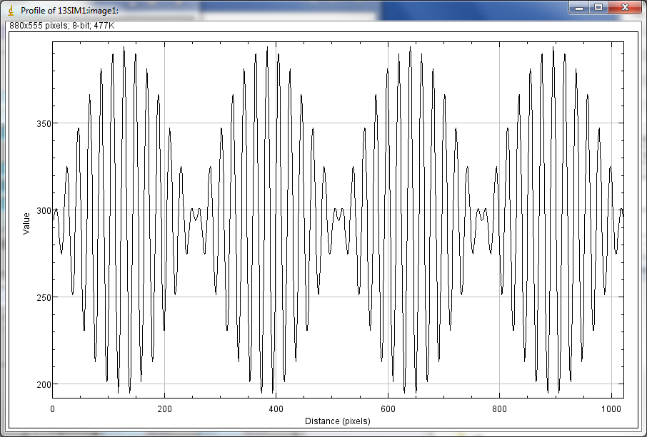
If the Frequency is an integer then there will be an integer number of sine wave periods across the image, and these will appear to be stationary from one image to the next. If Frequency is not an integer then there will be a non-integer number of periods across the image, and the sine wave will appear to move from one image to the next. This is because Count[X,Y] is not reset to 0 for each new image.
In monochrome mode the following equation is used to construct each image:
    Value[i,j] = Gain * (Offset + (Noise * random) +
                         XSine1[i] (+ or *) XSine2[i] +
                         YSine1[j] (+ or *) YSine2[j])
where
Gain is the overall image gain defined in ADBase.template.Noise is the overall noise level in the image.random is a random number in the range -1 to 1 that is different
for each pixel in the image.i is an index that goes from 0 to the image dimension SizeX.j is an index that goes from 0 to the image dimension SizeY.XSine1, XSine1, YSine1, YSine2 are the 4 sine waves described above.(+ or -) is either addition or multiplication depending on the value
of XSineOperation and YSineOperation described above.In color mode (NDColorMode=NDColorModeRGB1, RGB2 or RGB3) the following equations are used to construct each image:
    Red[i,j]   = Gain * GainRed   * (Offset + (Noise * random) + XSine1[i])
    Green[i,j] = Gain * GainGreen * (Offset + (Noise * random) + YSine1[j]
    Blue[i,j]  = Gain * GainBlue  * (Offset + (Noise * random) +
                                    (XSine2[i] + YSine2[j]) / 2))
where the values have the same meaning as for monochrome images, and GainRed, GainGreen, and GainBlue are the same as for Linear Ramp mode explained above. Note that the red image is a single sine wave in the X direction (XSine1), the green image is a single sine wave in the Y direction (YSine1), and the blue image is the sum of XSine2 and YSine2.
The simDetector driver is created with the simDetectorConfig command, either from C/C++ or from the EPICS IOC shell.
int simDetectorConfig(const char *portName,
                      int maxSizeX, int maxSizeY, int dataType,
                      int maxBuffers, size_t maxMemory,
                      int priority, int stackSize)
The simDetector-specific fields in this command are:
maxSizeX Maximum number of pixels in the X direction for the simulated
detector.maxSizeY Maximum number of pixels in the Y direction for the simulated
detector. dataType Initial data type of the detector data. These are the enum
values for NDDataType_t, i.e.
For details on the meaning of the other parameters to this function refer to the detailed documentation on the simDetectorConfig function in the simDetector.cpp documentation and in the documentation for the constructor for the simDetector class.
There an example IOC boot directory and startup script (iocBoot/iocSimDetector/st.cmd) provided with areaDetector.
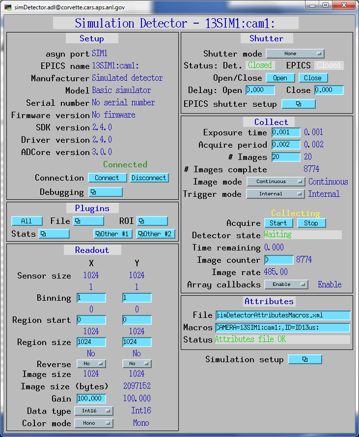
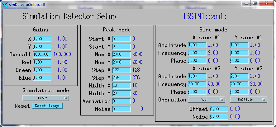
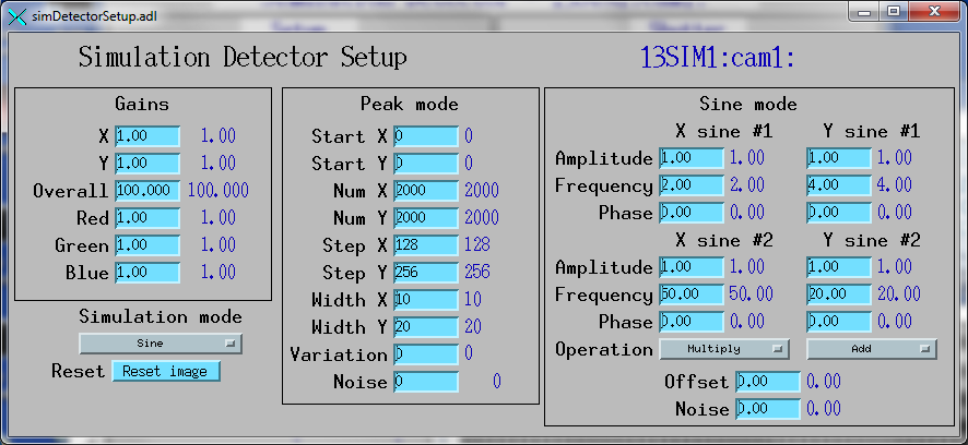
The following is the MEDM screen simDetector.adl for the simulation detector.
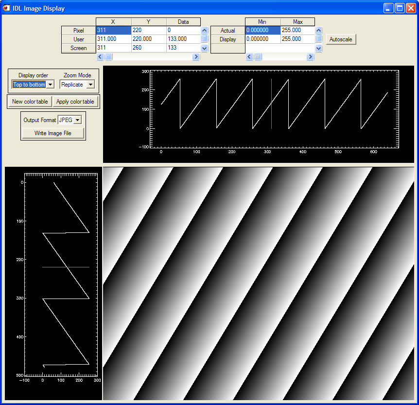
The following is an IDL epics_ad_display screen using image_display to display the simulation detector in monochrome linear ramp mode.
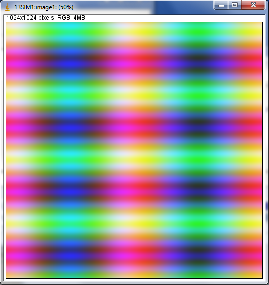
The following is an ImageJ plugin EPICS_AD_Viewer screen displaying the simulation detector in color linear ramp mode.
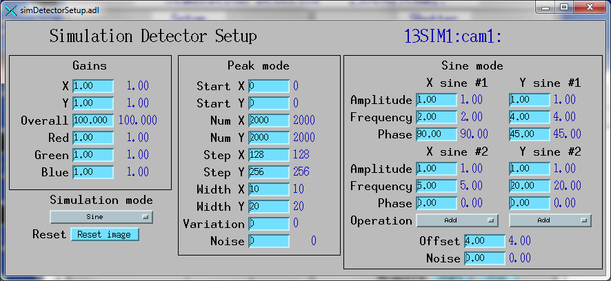
This is an example of the MEDM screen that provides access to the specific parameters for the simulation detector. In this case Peaks mode is selected.
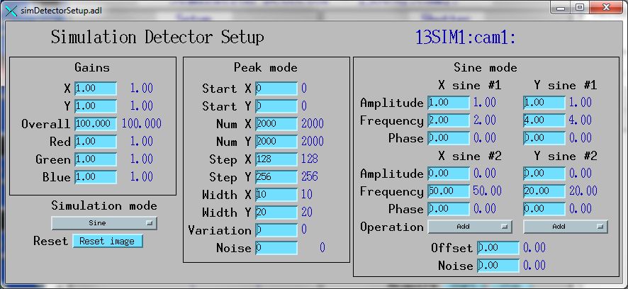
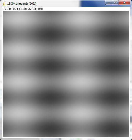
This is a simple example of Sine mode. The XSine1 frequency is 2 and the YSine1 frequency is 4. The Sine2 amplitudes are zero, so there is a single sine wave in each direction.
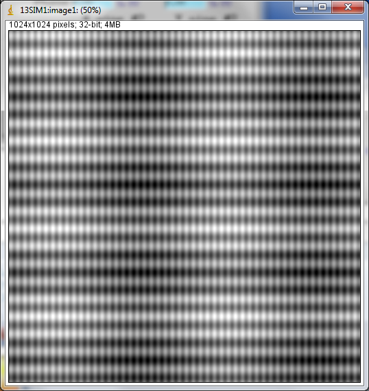
This is a complex example of Sine mode. There are 2 sine waves in each direction, with multiplication in X and addition in Y.
This is a example of Sine mode in RGB1 color mode.