prosilica.adl
This is an EPICS areaDetector driver for Gigabit Ethernet and Firewire cameras from Allied Vision Technologies, who purchased Prosilica. The driver is supported under Windows, Linux and Mac OS X using the vendor library provided for those operating systems.
This driver inherits from ADDriver. It implements nearly all of the parameters in asynNDArrayDriver.h and in ADArrayDriver.h. It also implements a number of parameters that are specific to the Prosilica cameras. The prosilica class documentation describes this class in detail.
The driver redefines the choices for several of the parameters defined in ADDriver.h. The ADTriggerMode choices for the Prosilica are:
The Prosilica supports hardware timing input and output signals that are supported in the driver.
The NDDataType choices for the Prosilica are:
The NDColorMode choices for the Prosilica are:
The color Prosilica cameras are also capable of various YUV color formats but these are not supported in the driver. They may be added in a future release.
The Prosilica driver implements the following parameters in addition to those in asynNDArrayDriver.h and ADDriver.h:
| Parameter Definitions in prosilica.cpp and EPICS Record Definitions in prosilica.template | ||||||
| Parameter index variable | asyn interface | Access | Description | drvInfo string | EPICS record name | EPICS record type |
|---|---|---|---|---|---|---|
| Bayer Color Conversion | ||||||
| PSBayerConvert | asynInt32 | r/w |
Color conversion when NDColorMode is Bayer: None: Raw Bayer images are passed to the plugins RGB1: Bayer images are converted to RGB1 RGB2: Bayer images are converted to RGB2 RGB3: Bayer images are converted to RGB3 Having the camera send Bayer images uses 3 times less network bandwidth than sending RGB1 images. It does place more CPU load on the host to convert from Bayer to RGB, but this is often an acceptable tradeoff. |
PS_BAYER_CONVERT |
$(P)$(R)BayerConvert $(P)$(R)BayerConvert_RBV |
mbbo
mbbi |
| Trigger and I/O Control | ||||||
| PSTriggerEvent | asynInt32 | r/w |
The edge or level for the selected trigger signal when ADTriggerMode=Sync In 1 to
SyncIn 4. Allowed values are: Rising edge Falling edge Any edge High level Low level |
PS_TRIGGER_EVENT |
$(P)$(R)TriggerEvent $(P)$(R)TriggerEvent_RBV |
mbbo
mbbi |
| PSTriggerDelay | asynFloat64 | r/w | The delay in seconds between the trigger signal and when the frame is actually acquired. Minimum value is 1 microsecond. | PS_TRIGGER_DELAY |
$(P)$(R)TriggerDelay $(P)$(R)TriggerDelay_RBV |
ao
ai |
| PSTriggerOverlap | asynInt32 | r/w |
Controls the behavior when an external trigger signal arrives before the camera
is ready for the next trigger. Allowed values are: Off - the external trigger is ignored Previous frame - the external trigger is latched and triggers the next frame when the current frame completes |
PS_TRIGGER_OVERLAP |
$(P)$(R)TriggerOverlap $(P)$(R)TriggerOverlap_RBV |
mbbo
mbbi |
| PSTriggerSoftware | asynInt32 | r/w | Processing this record performs a software trigger if ADTriggerMode=Software. | PS_TRIGGER_SOFTWARE | $(P)$(R)TriggerSoftware | bo |
| PSSyncIn1Level | asynInt32 | r/o | The level of the Sync In 1 signal | PS_SYNC_IN_1_LEVEL | $(P)$(R)SyncIn1Level_RBV | bi |
| PSSyncIn2Level | asynInt32 | r/o | The level of the Sync In 2 signal | PS_SYNC_IN_2_LEVEL | $(P)$(R)SyncIn2Level_RBV | bi |
| PSSyncOut1Mode | asynInt32 | r/w |
The mode of the Sync Out 1 signal. Allowed values are:
GPO (general purpose output) AcqTrigReady FrameTrigReady FrameTrigger Exposing FrameReadout Imaging Acquiring SyncIn1 SyncIn2 SyncIn3 SyncIn4 Strobe1 Strobe2 Strobe3 Strobe4 |
PS_SYNC_OUT_1_MODE |
$(P)$(R)SyncOut1Mode
$(P)$(R)SyncOut1Mode_RBV |
mbbo
mbbi |
| PSSyncOut1Level | asynInt32 | r/w | The level of the Sync Out 1 signal. This is only programmable when SyncOut1Mode=GPO. | PS_SYNC_OUT_1_LEVEL |
$(P)$(R)SyncOut1Level $(P)$(R)SyncOut1Level_RBV |
bo bi |
| PSSyncOut1Invert | asynInt32 | r/w | Flag to invert the Sync Out 1 signal. | PS_SYNC_OUT_1_INVERT |
$(P)$(R)SyncOut1Invert $(P)$(R)SyncOut1Invert_RBV |
bo bi |
| PSSyncOut2Mode | asynInt32 | r/w | The mode of the Sync Out 2 signal. Allowed values are the same as for PSSyncOut1Mode. | PS_SYNC_OUT_2_MODE |
$(P)$(R)SyncOut2Mode
$(P)$(R)SyncOut2Mode_RBV |
mbbo
mbbi |
| PSSyncOut2Level | asynInt32 | r/w | The level of the Sync Out 2 signal. This is only programmable when SyncOut2Mode=GPO. | PS_SYNC_OUT_2_LEVEL |
$(P)$(R)SyncOut2Level $(P)$(R)SyncOut1Level_RBV |
bo bi |
| PSSyncOut2Invert | asynInt32 | r/w | Flag to invert the Sync Out 2 signal. | PS_SYNC_OUT_2_INVERT |
$(P)$(R)SyncOut2Invert $(P)$(R)SyncOut2Invert_RBV |
bo bi |
| PSSyncOut3Mode | asynInt32 | r/w | The mode of the Sync Out 3 signal. Allowed values are the same as for PSSyncOut1Mode. | PS_SYNC_OUT_3_MODE |
$(P)$(R)SyncOut3Mode
$(P)$(R)SyncOut3Mode_RBV |
mbbo
mbbi |
| PSSyncOut3Level | asynInt32 | r/w | The level of the Sync Out 3 signal. This is only programmable when SyncOut3Mode=GPO. | PS_SYNC_OUT_3_LEVEL |
$(P)$(R)SyncOut3Level $(P)$(R)SyncOut3Level_RBV |
bo bi |
| PSSyncOut3Invert | asynInt32 | r/w | Flag to invert the Sync Out 3 signal. | PS_SYNC_OUT_3_INVERT |
$(P)$(R)SyncOut3Invert $(P)$(R)SyncOut3Invert_RBV |
bo bi |
| PSStrobe1Mode | asynInt32 | r/w |
The mode of the Strobe 1 signal. The Strobe signals are based on the following values,
but allow for changing the delay and width relative to the underlying value. Any
of the outputs can be set to the Stobe1 value, rather than the raw values of these
signals. Allowed values are:
AcqTrigReady FrameTrigReady FrameTrigger Exposing FrameReadout Acquiring SyncIn1 SyncIn2 SyncIn3 SyncIn4 |
PS_STROBE_1_MODE |
$(P)$(R)Strobe1Mode
$(P)$(R)Strobe1Mode_RBV |
mbbo
mbbi |
| PSStrobe1CtlDuration | asynInt32 | r/w | Flag to allow controlling the strobe duration. | PS_STROBE_1_CTL_DURATION |
$(P)$(R)Strobe1CtlDuration $(P)$(R)Strobe1CtlDuration_RBV |
bo bi |
| PSStrobe1Duration | asynFloat64 | r/w | The strobe duration if PSStrobe1CtlDuration is On. | PS_STROBE_1_DURATION |
$(P)$(R)Strobe1Duration $(P)$(R)Strobe1Duration_RBV |
ao ai |
| PSStrobe1Delay | asynFloat64 | r/w | The strobe delay relative to the underlying signal that the strobe is based on. | PS_STROBE_1_DELAY |
$(P)$(R)Strobe1Delay $(P)$(R)Strobe1Delay_RBV |
ao ai |
| Timestamp Control | ||||||
| PSResetTimer | asynInt32 | r/w | Resets the timestamp timer in the camera. If PSTimestampType is POSIX or EPICS then it also stores the current POSIX or EPICS time in the driver. | PS_RESET_TIMER | $(P)$(R)PSResetTimer | longout |
| PSTimestampType | asynInt32 | r/w |
Controls the type of timestamp in the timeStamp field of each NDArray. Choices are:
|
PS_TIMESTAMP_TYPE |
$(P)$(R)PSTimestampType $(P)$(R)PSTimestampType_RBV |
mbbo mbbi |
| Statistics Information | ||||||
| PSReadStatistics | asynInt32 | r/w | Read the Gigabit Ethernet statistics when 1 | PS_READ_STATISTICS | $(P)$(R)PSReadStatistics | longout |
| PSStatDriverType | asynOctet | r/o | Driver type | PS_DRIVER_TYPE | $(P)$(R)PSDriverType_RBV | stringin |
| PSStatFilterVersion | asynOctet | r/o | Packet filter version | PS_FILTER_VERSION | $(P)$(R)PSFilterVersion_RBV | stringin |
| PSStatFrameRate | asynFloat64 | r/o | Frame rate (Hz) | PS_FRAME_RATE | $(P)$(R)PSFrameRate_RBV | ai |
| PSByteRate | asynInt32 | r/w | Stream bytes per second in the PvAPI driver. This allows limiting the bandwidth that a camera uses. It also allows operation of GigE cameras on non-Gigabit Ethernet networks by decreasing the value to maximum that the network supports. The default of 115000000 allows full-speed operation on GigE networks. | PS_BYTE_RATE |
$(P)$(R)PSByteRate $(P)$(R)PSByteRate_RBV |
longout longin |
| PSPacketSize | asynInt32 | r/o | Actual packet size of Ethernet packets. When connecting to the camera the driver always automatically negotiates the largest packet size that the camera and IOC computer support. | PS_PACKET_SIZE | $(P)$(R)PSPacketSize_RBV | longin |
| PSStatFramesCompleted | asynInt32 | r/o | Number of frames completed | PS_FRAMES_COMPLETED | $(P)$(R)PSFramesCompleted_RBV | longin |
| PSStatFramesDropped | asynInt32 | r/o | Number of frames dropped | PS_FRAMES_DROPPED | $(P)$(R)PSFramesDropped_RBV | longin |
| PSStatPacketsErroneous | asynInt32 | r/o | Number of erroneous packets | PS_PACKETS_ERRONEOUS | $(P)$(R)PSPacketsErroneous_RBV | longin |
| PSStatPacketsMissed | asynInt32 | r/o | Number of missed packets | PS_PACKETS_MISSED | $(P)$(R)PSPacketsMissed_RBV | longin |
| PSStatPacketsReceived | asynInt32 | r/o | Number of received packets | PS_PACKETS_RECEIVED | $(P)$(R)PSPacketsReceived_RBV | longin |
| PSStatPacketsRequested | asynInt32 | r/o | Number of packets requested | PS_PACKETS_REQUESTED | $(P)$(R)PSPacketsRequested_RBV | longin |
| PSStatPacketsResent | asynInt32 | r/o | Number of packets resent | PS_PACKETS_RESENT | $(P)$(R)PSPacketsResent_RBV | longin |
| PSBadFrameCounter | asynInt32 | r/o | Number of bad frames | PS_BAD_FRAME_COUNTER | $(P)$(R)PSBadFrameCounter_RBV | longin |
The Prosilica driver is created with the prosilicaConfig command, either from C/C++ or from the EPICS IOC shell.
int prosilicaConfig(char *portName,
                    const char* cameraId,
                    int maxBuffers, size_t maxMemory,
                    int priority, int stackSize, int maxPvAPIFrames)
The cameraId string can be any of the following:
Using the UniqueId has the advantage that the cameras can be configured to use DHCP, and hence have non-predictable TCP/IP addresses. However, if the UniqueId is used then the areaDetector IOC must be on the same subnet as the camera, since cameras cannot be found by UniqueID through routers. The simplest way to determine the uniqueId of a camera is to run the Prosilica GigEViewer application, select the camera, and press the "i" icon on the bottom of the main window to show the camera information for this camera. The Unique ID will be displayed on the first line in the information window.
The IP address or IP DNS name can be used for cameras with fixed IP addresses, and must be used for cameras that are not on the local subnet.
The maxPvAPIFrames parameter controls how many frame buffers will be used by the PvAPI library. This is the last parameter in the prosilicaConfig command, and if it is absent the default value of 2 is used, which is sufficient in most circumstances. However, with very high frame rates or busy IOCs increasing this value can reduce dropped frames.
For details on the meaning of the other parameters to this function refer to the detailed documentation on the prosilicaConfig function in the prosilica.cpp documentation and in the documentation for the constructor for the prosilica class.
There an example IOC boot directory and startup script (iocBoot/iocProsilica/st.cmd) provided with areaDetector.
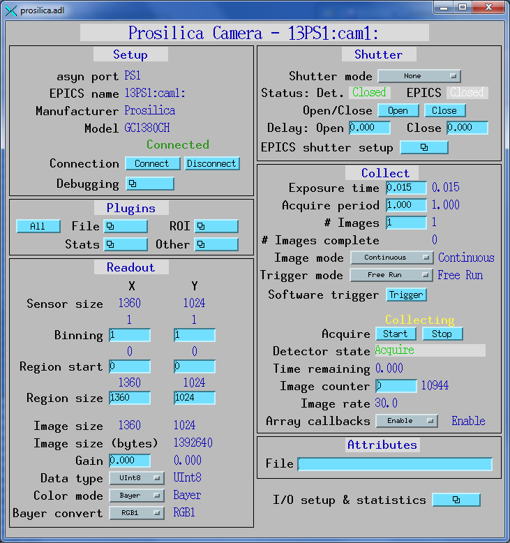
The following is the MEDM screen prosilica.adl.
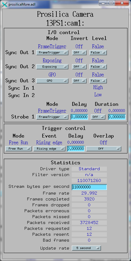
The following is the MEDM screen that provides access to the specific parameters for the Prosilica detector.
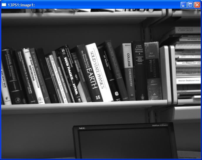
The following is an IDL epics_ad_display screen displaying the Prosilica detector images.
The Prosilica driver implements connection management. Cameras do not need to be accessible when the IOC starts up, and can be power-cycled or disconnected and reconnected from the Ethernet without restarting the IOC.
Whenever a new camera is detected on the network the Prosilica library issues a callback to the driver. If the driver is not currently connected to a camera it will attempt to connect when receiving the callback. This mechanism should work no matter how the camera is identified in the startup script, i.e. by Unique ID, IP address, or IP name. It is also possible to manually connect and disconnect the camera by using the $(P)$(R)AsynIO.CNCT PV, which is labeled "Connect" and "Disconnect" on the medm screen.
If the camera is not accessible when the IOC boots, or is power-cycled then the EPICS output records may not match the actual camera settings and readbacks. They can be made to agree by processing the output record, e.g. by pressing Enter or Return in the medm output widget. In the future this may be improved by sending all of the EPICS settings to the camera when it connects, though it is not clear if this would always be the desired behavior.