scan1, scan2, scan3, scan4, scanH (sscan)The example IOC startup script loads the scan.sb database from the SSCAN module. This loads 5 sscan records which can be used to perform up to 4-dimensional scans with any EPICS PV as positioners and detectors. The scan records are very useful with the Pilatus for scanning the ThresholdEnergy PV and plotting the counts in an ROI that includes the entire detector. This allows setting the energy threshold to detect the x-rays of interest.
EPICS startup script
pilatusROI.template is loaded with the following macro parameters:
| Macro parameter | Description |
|---|---|
$(DET) |
PV name prefix. This identifies this Pilatus detector from others that may be running on the same subnet. |
$(NXPIXELS) |
The number of pixels in the X (fast index) direction on the detector. This is 487 for the Pilatus 100K. |
$(NYPIXELS) |
The number of pixels in the Y (slow index) direction on the detector. This is 195 for the Pilatus 100K. |
$(NPIXELS) |
The total number of pixels on the detector. This is NXPIXELS*NYPIXELS=94965 for the Pilatus 100K. |
$(PORT) |
The name of the asyn port connected to the Pilatus via a TCP/IP socket. |
pilatusROI_N.template is loaded for each ROI with the following macro parameters:
| Macro parameter | Description |
|---|---|
$(DET) |
PV name prefix. This identifies this Pilatus detector from others that may be running on the same subnet. |
$(N) |
The number of this ROI. Starts with 1. |
$(XMIN) |
The minimum value of X for this ROI. Starts with 0. |
$(XMAX) |
The maximum value of X for this ROI. Starts with 0. |
$(YMIN) |
The minimum value of Y for this ROI. Starts with 0. |
$(YMAX) |
The maximum value of Y for this ROI. Starts with 0. |
$(BGD_WIDTH) |
The background width for this ROI. If BGD_WIDTH <=0 then no background subtraction is done, and NetCounts=TotalCounts. |
$(NCHANS) |
The maximum number of elements in the WFTotalCounts and WFNetCounts waveform arrays. This sets the maximum value of NImages for collecting ROI arrays. |
The pilatusROIs SNL program is started with the following macro parameters:
| Macro parameter | Description |
|---|---|
DET |
PV name prefix. This identifies this Pilatus detector from others that may be running on the same subnet. |
PORT |
The name of the asyn port connected to the Pilatus via a TCP/IP socket. |
NROIS |
The number of ROIs loaded in the substitutions file with pilatusROI_N.template. Maximum=32. |
The following is an example st.cmd startup script:
< envPaths

###
# Load the EPICS database file
dbLoadDatabase("$(PILATUS)/dbd/pilatus.dbd")
pilatus_registerRecordDeviceDriver(pdbbase)

###
# Create the asyn port to talk to the Pilatus on port 41234.
drvAsynIPPortConfigure("pilatus","gse-pilatus1:41234")
# Set the input and output terminators.
asynOctetSetInputEos("pilatus", 0, "\030")
asynOctetSetOutputEos("pilatus", 0, "\n")
# Define the environment variable pointing to stream protocol files.
epicsEnvSet("STREAM_PROTOCOL_PATH", "$(PILATUS)/pilatusApp/Db")

###
# Specify where save files should be
set_savefile_path(".", "autosave")

###
# Specify what save files should be restored.  Note these files must be
# in the directory specified in set_savefile_path(), or, if that function
# has not been called, from the directory current when iocInit is invoked
set_pass0_restoreFile("auto_settings.sav")
set_pass1_restoreFile("auto_settings.sav")

###
# Specify directories in which to to search for included request files
set_requestfile_path("./")
set_requestfile_path("$(AUTOSAVE)", "asApp/Db")
set_requestfile_path("$(CALC)",     "calcApp/Db")
set_requestfile_path("$(SSCAN)",    "sscanApp/Db")
set_requestfile_path("$(PILATUS)",  "pilatusApp/Db")

###
# Load the save/restore status PVs
dbLoadRecords("$(AUTOSAVE)/asApp/Db/save_restoreStatus.db", "P=PILATUS:")

###
# Load the substitutions for for this IOC
dbLoadTemplate("PILATUS_all.subs")
# Load an asyn record for debugging
dbLoadRecords("$(ASYN)/db/asynRecord.db", "P=PILATUS:,R=asyn1,PORT=pilatus,ADDR=0,IMAX=80,OMAX=80")

# Load sscan records for scanning
dbLoadRecords("$(SSCAN)/sscanApp/Db/scan.db", "P=PILATUS:,MAXPTS1=2000,MAXPTS2=200,MAXPTS3=20,MAXPTS4=10,MAXPTSH=2048")

###
# Set debugging flags if desired
#asynSetTraceIOMask("pilatus",0,2)
#asynSetTraceMask("pilatus",0,3)

###
# Start the IOC
iocInit

###
# Save settings every thirty seconds
create_monitor_set("auto_settings.req", 30, "P=PILATUS:")

###
# Start the SNL program
seq(pilatusROIs, "DET=PILATUS:, PORT=pilatus, NROIS=16")
The following is the substutitions file PILATUS_all.subs referenced above.
It creates 16 ROIS, and defines 5 valid ones: the entire chip, and the 4 quadrants of the chip:
ffile $(PILATUS)/db/pilatusROI.template {
pattern
{DET,       NXPIXELS,  NYPIXELS,  NPIXELS,   PORT}
{PILATUS:,       487,       195,    94965,   pilatus}
}

file $(PILATUS)/db/pilatusROI_N.template {
pattern
{DET,       N,  XMIN,   XMAX,  YMIN,  YMAX,  BGD_WIDTH,  NCHANS}
{PILATUS:,  1,     0,    486,     0,   194,          1,    2000}
{PILATUS:,  2,     0,    243,     0,    97,          1,    2000}
{PILATUS:,  3,     0,    243,    98,   194,          1,    2000}
{PILATUS:,  4,   244,    486,     0,    97,          1,    2000}
{PILATUS:,  5,   244,    486,    98,   194,          1,    2000}
{PILATUS:,  6,    -1,     -1,    -1,    -1,          1,    2000}
{PILATUS:,  7,    -1,     -1,    -1,    -1,          1,    2000}
{PILATUS:,  8,    -1,     -1,    -1,    -1,          1,    2000}
{PILATUS:,  9,    -1,     -1,    -1,    -1,          1,    2000}
{PILATUS:, 10,    -1,     -1,    -1,    -1,          1,    2000}
{PILATUS:, 11,    -1,     -1,    -1,    -1,          1,    2000}
{PILATUS:, 12,    -1,     -1,    -1,    -1,          1,    2000}
{PILATUS:, 13,    -1,     -1,    -1,    -1,          1,    2000}
{PILATUS:, 14,    -1,     -1,    -1,    -1,          1,    2000}
{PILATUS:, 15,    -1,     -1,    -1,    -1,          1,    2000}
{PILATUS:, 16,    -1,     -1,    -1,    -1,          1,    2000}
}
MEDM screens
The following show the MEDM screens that are used to control the pilatusROI software.
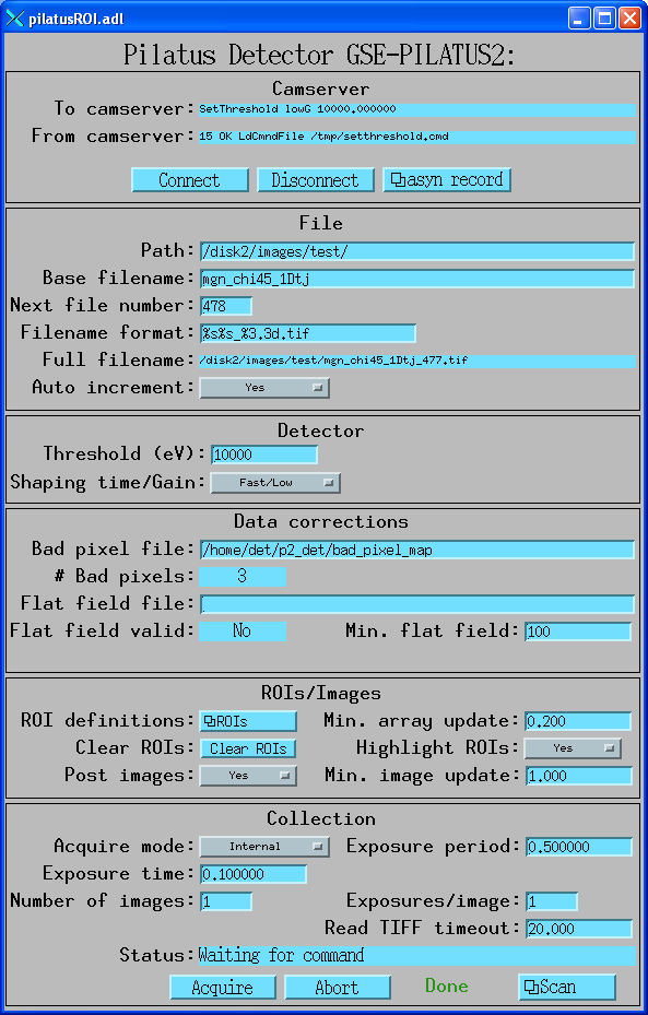
pilatusROI.adl is the main screen used to control the pilatusROI SNL
program. All records except those that are specific to each ROI are accessed through this
screen.
pilatusROI.adl
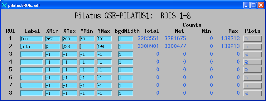
pilatus8ROIs.adl is used to define the ROIs, and to display the statistics for
each ROI. In this example there are 2 valid ROIs defined. ROI 1 is a small rectangle near the center
containing the Bragg diffraction peak from a crystal. ROI 2 is the entire chip.
pilatus8ROIs.adl
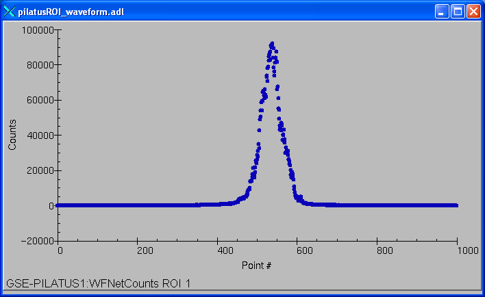
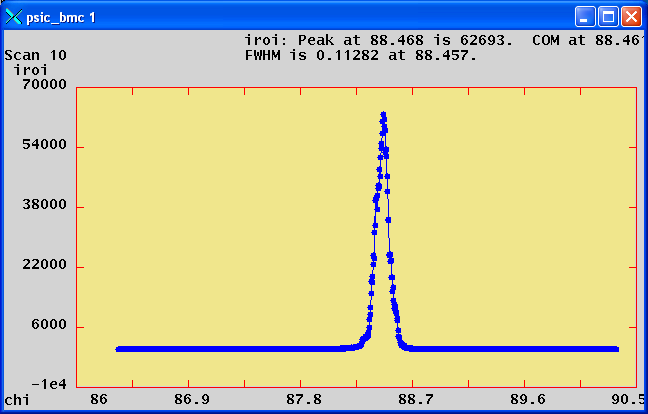
pilatusROI_waveform.adl is used to plot the net or total counts in an ROI when
NImages>1. In this example the plot is the net counts in ROI 1 as the diffractometer chi was scanned
+- 1 degree with 1000 points at .02 seconds/point. This was done with the SPEC command
lup chi -1 1 1000 .02using trajectory scanning on a Newport kappa diffractometer. This was a compound motor scan with the Newport XPS putting out pulses every .02 seconds. These pulses triggered the Pilatus in External Enable mode. The pilatusROI program read each TIFF file as it was created and updated this plot every 0.2 seconds. The total time to collect this scan with 1000 images was 20 seconds.
pilatusROI_waveform.adl
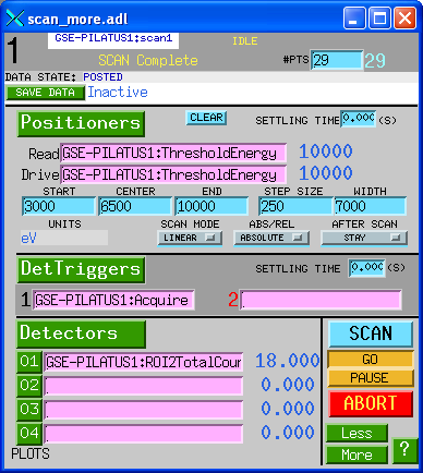
scan_more.adl is used to define a scan. In this example the sscan record is set up
to scan the ThresholdEnergy PV and to collect the total counts in ROI2, which was defined to include
the entire detector.
scan_more.adl
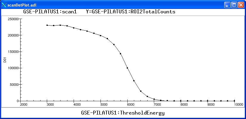
scanDetPlot.adl is used to plot the results of a scan after it is complete.
In this example the total counts in ROI 2 are plotted as a function of the ThresholdEnergy as it was
scanned from 3000 to 10000 eV in 250 eV steps. The source was Fe55, and the cut-off is at 6 keV, as
expected for the Mn Ka and Mn Kb x-rays that this source produces.
scanDetPlot.adl
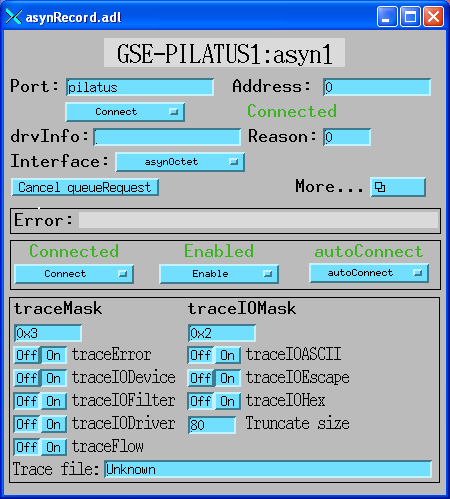
asynRecord.adl is used to control the debugging information printed by the asyn TCP/IP driver
(asynTraceIODriver) and the SNL program (asynTraceIODevice).
asynRecord.adl
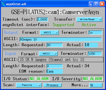
asynOctet.adl can be used to send any command to camserver and display the response. It can
be loaded from the More menu in asynRecord.adl above.
asynOctet.adl
IDL Image Display Client
epics_image_display
that can be used to display the ImageData PV that pilatusROI sends over EPICS. This IDL
client is available as source code (which requires an IDL license), and also as a pre-built IDL .sav
file that can be run for free under the IDL Virtual Machine. This IDL program can run on any machine that IDL
runs on, and that has the ezcaIDL shareable library built for it. This includes Windows, Linux, Solaris, and Mac.
epics_image_display is included in the
CARS IDL imaging software.
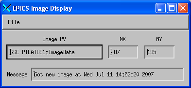
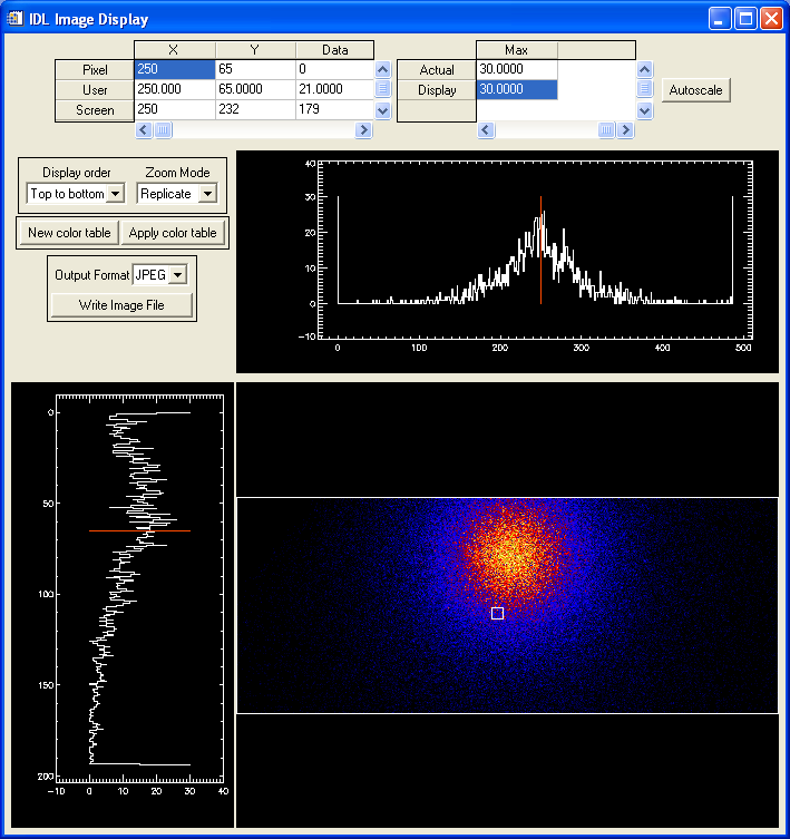
The control window for epics_image_display is shown below. It has fields to input the name of
the EPICS PV with the image data, which is $(DET)ImageData in the case of pilatusROI. It also has fields
for the number of pixels in the X and Y directions. This is needed because EPICS waveform records are
1-dimensional only, and so do not contain the information on the number of rows and columns in the image.
Main window for IDL epics_image_display
epics_image_display uses the routine
image_display.pro
to display the images. This routine displays row and column profiles as the cursor is moved. It allows
changing the color lookup tables, and zooming in and out with the left and right mouse buttons. The following
is an example of image_display displaying a Pilatus image with an Fe55 source in front of the detector.
IDL image_display with Fe55 radioactive source
SPEC interface
# need some more globals (kludge)
global    PILATUS_ROI_PV
global    PILATUS_IMGPATH_PV
global    PILATUS_FNAME_PV
global    PILATUS_FILENUMBER_PV
global    PILATUS_FILEFORMAT_PV
global    PILATUS_EXPSRTM_PV
global    PILATUS_NFRAME_PV
global    PILATUS_EXPPRD_PV
global    PILATUS_NEXPFRM_PV
global    PILATUS_ACQ_PV
global    PILATUS_ACQMODE_PV

###############################################################
def _setup_img '{
     local j, str

     # PILATUS_PREFIX should be detector aquisition pv (GSE-PILATUS1:)
     if ( PILATUS_PREFIX == "") PILATUS_PREFIX = "GSE-PILATUS1:"
     PILATUS_PREFIX = getval("Enter PILATUS pv prefix",PILATUS_PREFIX)

     # rois pvs
     PILATUS_ROI_PV    = PILATUS_PREFIX "ROI1NetCounts"
     PILATUS_IMGPATH_PV = PILATUS_PREFIX "FilePath"
     PILATUS_FNAME_PV   = PILATUS_PREFIX "Filename"
     PILATUS_FILENUMBER_PV   = PILATUS_PREFIX "FileNumber"
     PILATUS_FILEFORMAT_PV = PILATUS_PREFIX "FileFormat"
     PILATUS_EXPSRTM_PV = PILATUS_PREFIX "ExposureTime"
     PILATUS_NFRAME_PV  = PILATUS_PREFIX "NImages"
     PILATUS_EXPPRD_PV  = PILATUS_PREFIX "ExposurePeriod"
     PILATUS_NEXPFRM_PV = PILATUS_PREFIX "NExposures"
     PILATUS_ACQ_PV     = PILATUS_PREFIX "Acquire"
     PILATUS_ACQMODE_PV = PILATUS_PREFIX "AcquireMode"
...

def epics_pilatus_count '{
...
     # write to data base fields
     # Need to convert path from string to byte array
     # Note: we use the "wait" parameter in epics_put here (new to spec5.7.02) so that
     # it uses ca_put_callback, to know that all PVs have been processed
     # before we start counting.  Use 1 second timeout, will actually be
     # much faster than this unless something is wrong.
     array _temp[256]
     _temp = PILATUS_IMAGE_DIR
     # Do not change path for now
     #epics_put(PILATUS_IMGPATH_PV,_temp, 1)
     epics_put(PILATUS_FNAME_PV,img_fname, 1)
     epics_put(PILATUS_FILENUMBER_PV,NPTS, 1)
     epics_put(PILATUS_FILEFORMAT_PV,_fileformat, 1)
     epics_put(sc_prtm_pv,cnt_time_val, 1)
     epics_put(PILATUS_EXPSRTM_PV,cnt_time_val, 1)
     epics_put(PILATUS_ACQMODE_PV,0, 1)  # Internal trigger
     epics_put(PILATUS_NFRAME_PV, 1, 1)
     epics_put(PILATUS_NEXPFRM_PV, 1, 1)


def user_getcounts '{
    local pv_roi, j, pv

...
   # using image_count routine
    } else if ( EPICS_COUNT == 4 ) {
        S[iroi] = 0
        S[iroi] = epics_get(PILATUS_ROI_PV)
Performance measurements
- AcquireMode=Internal, NImages=1000, ExposureTime=.005, ExposurePeriod=.01, NExposures=1. The time to collect this series should be exactly 10.0 seconds. The actual time was measured using the EPICS camonitor program. It printed the time when acquisition was started (Acquire changed to Busy) and when acquisition was complete (Acquire changed to Done). The time was 10.274 seconds. This includes the time for camserver to save all 1000 images to disk (366 MB), and for pilatusROI to read each file, correct the bad pixels and flat field, compute the ROIs, and post the ROIs to EPICS. It also posted the images to EPICS at 1Hz (10 images total). The total additional time was less than 0.3 seconds for all 1000 images.
- AcquireMode=Internal, NImages=1, ExposureTime=.01, NExposures=1. An EPICS sscan record was used to collect 1000 points. There were no positioner PVs (to eliminate motor overhead). The only detector trigger was the pilatusROI Acquire PV. The only detector PV was ROI1TotalCounts. In this mode camserver is being told to individually collect each file. If there were no overhead then time to collect this series should be exactly 10.0 seconds. The actual time measured using the EPICS camonitor program was 49.161 seconds. The overhead is thus 39.161 seconds, or 39 ms per point. In this single-frame mode pilatusROI is thus able to collect >20 images/second. For comparison, another measurement was done using the same EPICS sscan record, but using a Joerger VSC16 scaler as the detector trigger and detector. The preset time was also .01 seconds. The elapsed time for a 1000 point scan was 16.068 seconds, so the overhead was 6.068 seconds, or 6 ms per point.
- AcquireMode=Ext. Enable, NImages=1000, NExposures=1.
SPEC was used to collect 1000 points using
trajectory scanning mode
with the Newport XPS motor controller. The following SPEC command was used:
lup chi -2 2 1000 .015This tells SPEC to do a relative scan of the chi axis from -2 degrees to +2 degrees with 1000 points at .015 seconds/point. On our kappa diffractometer this entails a coordinated motion of the phi, kappa and omega axes. The EPICS trajectory scanning software downloads the non-linear trajectory that SPEC computes into the XPS controller, which executes it. As the motors are moving the XPS outputs synchronization pulses at the period of the collection time, .015 seconds in this case. These pulses are stretched (see Hardware notes below) and used as the external input to the Pilatus. The time to execute this scan should be 15.0 seconds. The actual time was 16.3 seconds, measured using camonitor on the Acquire PV. Again, this includes the time for camserver to save all 1000 images to disk (366 MB), and for pilatusROI to read each file, correct the bad pixels and flat field, compute the ROIs, and post the ROIs to EPICS. It also posted the images to EPICS at 1Hz (15 images total). The total additional time was less than 1.3 seconds for all 1000 images. As soon as the acquisition was complete SPEC plotted the net counts in the first ROI (containing the Bragg peak) as follows:1000 point SPEC scan with 15 ms per point collected in 16.3 seconds
For comparison this identical scan was executed in traditional step-scanning mode, where the motors stopped at each point in the scan. The Pilatus was run in Internal mode with NImages=1. The total time for the scan was 870 seconds (more than 14 minutes), compared to 16.3 seconds in trajectory mode. Most of this overhead is the settling time for the motors, with only a small fraction due to the Pilatus single-exposure mode. The trajectory scanning mode is thus more than 50 times faster to execute the identical SPEC scan.
Hardware notes
Trigger pulses
The Pilatus supports 3 types of external triggering. In External Trigger mode (the camserver ExtTrigger command) the Pilatus uses the programmed values of ExposureTime, ExposurePeriod, NImages and NExposures. It waits for a single external trigger, then waits for Delay seconds and then collects the entire sequence. It is very similar to Internal mode with NImages>1, except that it waits for a trigger to begin collecting the sequence.In External Enable mode (the camserver ExtEnable command) the Pilatus uses the external signal to control acquisition. Only NImages and NExposures are used, ExposureTime and ExposurePeriod are not used. When the signal is high the detector counts, and on the transition to low it begins its readout.
In External MultiTrigger Mode (the camserver ExtMTrigger command) the Pilatus uses the programmed ExposureTime, in addition to NImages and NExposures. Each external trigger pulse causes the Pilatus to collect one image at the programmed exposure time. This mode works well with a trigger source like the Newport motor controllers or the SIS380x multichannel scaler, that put out a short trigger pulse for each image. One only needs to take care that the time between external trigger pulses is at least 4msec longer than the programmed exposure time, to allow time for the detector to read out before the next trigger pulse arrives.
When using the External Enable mode, we use an inexpensive analog pulse generator to convert the trigger pulses from the MM4005 and XPS to a form suitable for External Enable mode with the Pilatus. This is the solution we have developed that seems to be reliable:
- The synchonization pulses from the Newport MM4005 or XPS controller are input into the external next pulse (channel advance, control signal 1) input of the SIS3801 multiscaler. This is the normal configuration used for MCS counting without the Pilatus in trajectory scanning mode.
- The Copy In Progress (CIP) output of the SIS3801 (control signal 5) is connected to the Trigger Input of a
Tenma TGP110 10 MHz Pulse Generator. CIP will output a pulse whenever the SIS3801 does a channel advance,
either in external mode with the motor controller pulse input, or in internal timed channel advance mode.
The TGP100 Pulse Generator is configured as follows:
- Trigger Input connected to CIP output of SIS3801.
- Triggered mode.
- Complement output.
- Pulse duration set with knobs to 3msec.
- TTL Output connected to the External Input of the Pilatus.
- With this configuration the SIS3801 CIP output is normally at 5V, and outputs a 0V pulse 1 microsecond long. The trailing (rising) edge of that pulse triggers the TGP110. The TGP110 TTL output is also normally at 5V, and outputs a 0V pulse 3 milliseconds long each time the SIS3801 pulses. That output is connected to the Pilatus External Input. In External Enable mode when Pilatus External Input is high the Pilatus is counting. When the External Input is low the Pilatus reads out. The readout time is set via the knobs on the pulse generator to be 3 ms, which is close to the minimum time allowed on the Pilatus.
Detector Voltage
When we were initially testing the Pilatus in the lab, we had many errors in External Enable mode, where it did not seem to be seeing the external pulses. camserver would get DMA timeouts, and need to be restarted. Dectris said these were happening because the cables on our detector are longer than normal, and the voltage drop from the power supply to the detector was leading to marginal voltage values. They suggested shortening the cables or increasing the supply voltage slightly. When moving the detector to the hutch these problems initially went away. However, they then recurred, and we fixed the problem by increasing the power supply voltage from 4.4 to 4.7 volts at the detector.Dectris has since informed me that they have increased the power supply voltage on all new Pilatus systems, so this should no longer be an issue.
Restrictions
- Limited to TIFF file format. camserver can save files in other formats, but pilatusROI can currently only read TIFF files. Furthermore, it has a very simple TIFF reader. It does not read the TIFF tags at all, but simply assumes that there is a 4096 byte header, followed by the 32-bit image data. The size of the image data is controlled by the NXPixels and NYPixels PVs, which thus must be correctly set.
- The EPICS IOC should be run on the same computer as camserver. This is not strictly necessary, and places a small additional load on the CPU and network on that computer. However, we have found that TIFF files are available to be read within 10ms after camserver says they have been written if the IOC is running on the same machine as camserver. This is true even if the files are being saved on a remote NFS or SMB file system. On the other hand, if the IOC and camserver are running on separate machines, then the filesystem can wait up to 1 second after camserver says the TIFF file has been written before the IOC can read it. This is true even if the files are being written to the computer that the IOC is running on! This 1 second delay is often unacceptable for fast single-exposure scans, i.e. with NImages=1.
- pilatusROI keeps retrying to read each TIFF file until the modification date of the TIFF file is after the time that the exposure command was issued. If it did not do this check then it could be reading and displaying old files that happen to have the same name as the current files being collected. This check requires that the computer that is running the soft IOC must have its clock well synchronized with the clock on the computer on which the files are being written (i.e. the computer generating the file modification time). If the clocks are not synchronized then the files may appear to be stale when they are not, and pilatusROI will time out. pilatusROI actually tolerates up to 10 second clock skew betweeen the computers but any more than this may lead to problems.
- The Abort PV does not always work because camserver does not reliably implement the "K" command to stop an exposure sequence. In particular with NImages>1 camserver seems to often ignore the K command completely, even with exposure times/periods as long as 10 seconds. With NImages=1 it does kill the exposure after a few seconds.
- The following items are hardcoded in the SNL program. They can be changed before compiling if necessary.
Some could be changed to be EPICS PVs, so they could be controlled at run-time, but others must be defined
at compile time because of limitations in the SNL semantics.
- MAX_MESSAGE_SIZE=256 The maximum size of message to/from camserver.
- MAX_FILENAME_LEN=256 The maximum size of a complete file name including path and extension.
- FILE_READ_DELAY=.01 seconds. The time between polling to see if the TIFF file exists or if it is the expected size.
- MAX_BAD_PIXELS=100 The maximum number of bad pixels.
- MAX_ROIS=32 The maximum number of ROIs
- MAX_CHANS=2000 The maximum number of points in the ROI waveform arrays.
- MAX_PIXELS=94965 The maximum number of pixels in the ImageData array. Because of SNL semantics limitations this value must be defined at compile time, and cannot be changed at run time.
- MAX_READ_ERRORS=3 The maximum number of TIFF file read errors before the SNL gives up and aborts acquisition.