pilatusDetector.adl
This is an EPICS areaDetector driver for the Pilatus pixel array detectors from Dectris.
The interface to the detector is via a TCP/IP socket interface to the camserver server that Dectris provides. The camserver program must be started before the areaDetector software is started, typically by running the camonly script provided by Dectris.
The camserver program saves the data to disk as TIFF or CBF files. The areaDetector software reads these disk files in order to read the data, because camserver does not provide another mechanism to access the data. If camserver is saving TIFF files then the driver reads the TIFFImageDescription tag from the TIFF file. This is a long string that camserver writes to the file containing all of the detector settings, including threshold, energy, etc. The driver adds this information to the NDArray using an NDAttribute called TIFFImageDescription. The NDFileTIFF plugin in ADCore R2-6 was changed to write this complete attribute to the TIFFImageDescription tag in the new TIFF file. It will also be written by the NDFileNetCDF, NDFileHDF5, and NDFileNexus plugins. However these plugins are currently limited to 256 character string attributes, so some of the information will be lost because the string is longer than 256 characters.
This driver inherits from ADDriver. It implements many of the parameters in asynNDArrayDriver.h and in ADArrayDriver.h. It also implements a number of parameters that are specific to the Pilatus detectors.The pilatusDetector class documentation describes this class in detail.
The following table describes how the Pilatus driver implements some of the standard driver parameters.
| Parameter Definitions in pilatusDetector.cpp and EPICS Record Definitions in pilatus.template | ||
| Parameter index variable | EPICS record name | Description |
|---|---|---|
| ADTriggerMode | $(P)$(R)TriggerMode |
The driver redefines the choices for the ADTriggerMode parameter (record $(P)$(R)TriggerMode)
from ADDriver.h. The choices for the Pilatus are:
Exposure,
ExtEnable, ExtTrigger, and ExtMTrigger respectively.
Alignment mode uses the Exposure command as well, but continuously
takes images into the same temporary file (alignment.tif). |
| ADAcquireTime | $(P)$(R)AcquireTime | Controls the acquisision time in all modes except External Enable. In External Enable mode the timing is controlled entirely by the external trigger line. However, even in ExternalEnable mode AcquireTime is used by camserver and by the driver to estimate how long the acquisition will take. Hardware timeouts will occur if the actual time to acquire differs significantly from the estimated time based on AcquireTime and AcquirePeriod. |
| ADNumImages | $(P)$(R)NumImages | Controls the number of images to acquire. It applies in all trigger modes except Alignment. |
| ADAcquirePeriod | $(P)$(R)AcquirePeriod | Controls the exposure period in seconds in Internal or External Trigger modes when NumImages >1. In External Enable mode the timing is controlled entirely by the external trigger line. However, even in ExternalEnable mode AcquirePeriod is used by camserver and by the driver to estimate how long the acquisition will take. Hardware timeouts will occur if the actual time to acquire differs significantly from the estimated time based on AcquireTime and AcquirePeriod. |
| ADNumExposures | $(P)$(R)NumExposures | Controls the number of exposures per image. It is most useful in External Enable mode, but it can be set in any mode. |
| ADAquire | $(P)$(R)Acquire | Controls the acquisition. Setting this to 1 starts image acquisition. The driver sets the record to 0 when acquisition is complete. This means an entire acquisition series if NImages >1. Setting this to 0 aborts an acquisition. If the driver was currently acquiring imges then this record will cause the "Stop" and "K" (Kill) commands to be sent to camserver. |
| NDFilePath | $(P)$(R)FilePath | Controls the path for saving images. It must be a valid path for camserver and for the areaDetector driver, which is normally running in an EPICS IOC. If camserver and the EPICS IOC are not running on the same machine then soft links will typically be used to make the paths look identical. |
| NDFileTemplate | $(P)$(R)FileTemplate |
camserver uses the file extension to determine what format to save the files in.
The areaDetector Pilatus driver only supports TIFF and CBF files, so the extension
should be .tif or .cbf. When saving multiple images (NImages>1) camserver has its
own rules for creating the names of the individual files. The rules are as follows.
The name constructed using the algorithm described for NDFileTemplate under
File Saving Parameters is used as a basename. The following examples show
the interpretation of the basename.
Basename            Files produced

test6.tif           test6_00000.tif,  test6_00001.tif, ...
test6_.tif          test6_00000.tif,  test6_00001.tif, ...
test6_000.tif       test6_000.tif,    test6_001.tif, ...
test6_014.tif       test6_014.tif,    test6_015.tif, ...
test6_0008.tif      test6_0008.tif,   test6_0009.tif, ...
test6_2_0035.tif    test6_2_0035.tif, test6_2_0036.tif, ...
The numbers following the last '_' are taken as a format template, and as a start
value. The minimum format is 3; there is no maximum; the default is 5. The format
is also constrained by the requested number of images. |
It is useful to load and enable an NDPluginStats plugin that gets its data from the Pilatus driver. The MaxValue_RBV PV for that plugin can be monitored to make sure that the 20-bit limit of 1,048,575 is not being approached in any pixel.
The Pilatus driver implements the following parameters in addition to those in asynNDArrayDriver.h
and ADDriver.h:. Note that to reduce the width of this table the parameter index
variable names have been split into 2 lines, but these are just a single name, for
example PilatusDelayTime.
| Parameter Definitions in pilatusDetector.cpp and EPICS Record Definitions in pilatus.template | ||||||
| Parameter index variable | asyn interface | Access | Description | drvInfo string | EPICS record name | EPICS record type |
|---|---|---|---|---|---|---|
|
Pilatus DelayTime |
asynFloat64 | r/w | Delay in seconds between the external trigger and the start of image acquisition. It only applies in External Trigger mode | DELAY_TIME | $(P)$(R)DelayTime | ao |
|
Pilatus Threshold |
asynFloat64 | r/w | Threshold energy in keV. camserver uses this value to set the discriminators in each pixel. It is typically set to the incident x-ray energy ($(P)$(R)Energy), but sometimes other values may be preferable. | THRESHOLD |
$(P)$(R)ThresholdEnergy $(P)$(R)ThresholdEnergy_RBV |
ao ai |
|
Pilatus ThresholdApply |
asynInt32 | r/w | Apply the threshold value. Setting the threshold can be a time consuming operation, so if ThresholdAutoApply is No then ThresholdApply must be processed to actually send the threshold to camserver. | THRESHOLD_APPLY | $(P)$(R)ThresholdAppply | busy |
|
Pilatus ThresholdApply |
asynInt32 | r/w | Apply the threshold value. Setting the threshold can be a time consuming operation, so if ThresholdAutoApply is No then ThresholdApply must be processed to actually send the threshold to camserver. | THRESHOLD_APPLY | $(P)$(R)ThresholdApply | busy |
|
Pilatus ThresholdAutoApply |
asynInt32 | r/w | Automatically apply the threshold value whenever it changes. Setting the threshold can be a time consuming operation, so if ThresholdAutoApply is No then ThresholdApply must be processed to actually send the threshold to camserver. If it is Yes then the threshold value will be sent to camserver whenever it is changed. | THRESHOLD_AUTO_APPLY |
$(P)$(R)ThresholdAutoApply $(P)$(R)ThresholdAutoApply_RBV |
bo bi |
|
Pilatus Energy |
asynFloat64 | r/w | X-ray energy in keV. This is used by camserver to calculate the proper flat field corrrection. If Energy is 0 then the energy value sent to camserver is ThresholdEnergy*2. | ENERGY |
$(P)$(R)Energy $(P)$(R)Energy_RBV |
ao ai |
|
Pilatus GapFill |
asynInt32 | r/w | The value that camserver should write to the data file for the gaps between pixels in the detector. Choices are -2, 0, and -1. | GAP_FILL |
$(P)$(R)GapFill $(P)$(R)GapFill_RBV |
mbbo mbbi |
| N/A | N/A | r/w |
Gain menu. Controls the value of Vrf, which determines the shaping time and gain
of the input amplifiers. The allowed values are:
|
N/A | $(P)$(R)GainMenu | mbbo |
|
Pilatus Armed |
asynInt32 | r/o | Flag to indicate when the Pilatus is ready to accept external trigger signals (0=not ready, 1=ready). This should be used by clients to indicate when it is OK to start sending trigger pulses to the Pilatus. If pulses are send before Armed=1 then the Pilatus may miss them, leading to DMA timeout errors from camserver | ARMED | $(P)$(R)Armed | bi |
|
Pilatus ResetPower |
asynInt32 | r/w | Processing this record sends the "ResetModulePower delayTime" command to camserver. This cycles the high voltage and other detector supply voltages. This is particularly useful with the CdTe detectors when they have been exposed to a very strong signal. Cycling the power can erase the memory effects of oversaturation. The delayTime controls the amount of time to wait after turning off the power before turning it back on again. It is set by the ResetPowerTime record. | RESET_POWER | $(P)$(R)ResetPower | bo |
|
Pilatus ResetPowerTime |
asynInt32 | r/w | This record controls the number of seconds to wait after turning off the power before turning it back on again when the ResetPower record is processed. | RESET_POWER_TIME |
$(P)$(R)ResetPower $(P)$(R)ResetPower_RBV |
bo bi |
|
PilatusImage FileTmot |
asynFloat64 | r/w | Timeout in seconds when reading a TIFF or CBF file. It should be set to several seconds, because there can be delays for various reasons. One reason is that there is sometimes a delay between when an External Enable acquisition is started and when the first external pulse occurs. Another is that it can take some time for camserver processes to finish writing the files. | IMAGE_FILE_TMOT | $(P)$(R)ImageFileTmot | ao |
|
Pilatus BadPixelFile |
asynOctet | r/w |
Name of a file to be used to replace bad pixels. If this record does not point to
a valid bad pixel file then no bad pixel mapping is performed. The bad pixel map
is used before making the NDArray callbacks. It does not modify the data in the
files that camserver writes. This is a simple ASCII file with the following format:
badX1,badY1 replacementX1,replacementY1
badX2,badY2 replacementX2,replacementY2
...
The X and Y coordinates range from 0 to NXPixels-1 and NYPixels-1. Up to 100 bad
pixels can be defined. The bad pixel mapping simply replaces the bad pixels with
another pixel's value. It does not do any averaging. It is felt that this is sufficient
for the purpose for which this driver was written, namely fast on-line viewing of
ROIs and image data. More sophisticated algorithms can be used for offline analysis
of the image files themselves. The following is an example bad pixel file for a
GSECARS detector:
263,3   262,3
264,3   266,3
263,3   266,3
300,85  299,85
300,86  299,86
471,129 472,129
|
BAD_PIXEL_FILE | $(P)$(R)BadPixelFile | waveform |
|
Pilatus NumBadPixels |
asynInt32 | r/o | The number of bad pixels defined in the bad pixel file. Useful for seeing if the bad pixel file was read correctly. | NUM_BAD_PIXELS | $(P)$(R)NumBadPixels | longin |
|
Pilatus FlatFieldFile |
asynOctet | r/w |
Name of a file to be used to correct for the flat field. If this record does not
point to a valid flat field file then no flat field correction is performed. The
flat field file is simply a TIFF or CBF file collected by the Pilatus that is used
to correct for spatial non-uniformity in the response of the detector. It should
be collected with a spatially uniform intensity on the detector at roughly the same
energy as the measurements being corrected. When the flat field file is read, the
average pixel value (averageFlatField) is computed using all pixels with intensities
>PilatusMinFlatField. All pixels with intensity <PilatusMinFlatField in the
flat field are replaced with averageFlatField. When images are collected before
the NDArray callbacks are performed the following per-pixel correction is applied:
ImageData[i] =
    (averageFlatField *
    ImageData[i])/flatField[i];
|
FLAT_FIELD_FILE | $(P)$(R)FlatFieldFile | waveform |
|
Pilatus MinFlatField |
asynInt32 | r/w | The mimimum valid intensity in the flat field. This value must be set > 0 to prevent divide by 0 errors. If the flat field was collected with some pixels having very low intensity then this value can be used to replace those pixels with the average response. | MIN_FLAT_FIELD | $(P)$(R)MinFlatField | longout |
|
Pilatus FlatFieldValid |
asynInt32 | r/o | This record indicates if a valid flat field file has been read. 0=No, 1=Yes. | FLAT_FIELD_VALID | $(P)$(R)FlatFieldValid | bi |
|
Pilatus Wavelength |
asynFloat64 | r/w | MX wavelength to write to CBF and TIFF image header. | WAVELENGTH | $(P)$(R)Wavelength | ao |
|
Pilatus EnergyLow |
asynFloat64 | r/w | MX energy range low value to write to CBF and TIFF image header. | ENERGY_LOW | $(P)$(R)EnergyLow | ao |
|
Pilatus EnergyHigh |
asynFloat64 | r/w | MX energy range high value to write to CBF and TIFF image header. | ENERGY_HIGH | $(P)$(R)EnergyHigh | ao |
|
Pilatus DetDist |
asynFloat64 | r/w | MX detector distance to write to CBF and TIFF image header. | DET_DIST | $(P)$(R)DetDist | ao |
|
Pilatus DetVOffset |
asynFloat64 | r/w | MX detector vertical offset to write to CBF and TIFF image header. | DET_VOFFSET | $(P)$(R)DetVOffset | ao |
|
Pilatus BeamX |
asynFloat64 | r/w | MX beam X to write to CBF and TIFF image header. | BEAM_X | $(P)$(R)BeamX | ao |
|
Pilatus BeamY |
asynFloat64 | r/w | MX beam Y to write to CBF and TIFF image header. | BEAM_Y | $(P)$(R)BeamY | ao |
|
Pilatus Flux |
asynFloat64 | r/w | MX flux to write to CBF and TIFF image header. | FLUX | $(P)$(R)Flux | ao |
|
Pilatus FilterTransm |
asynFloat64 | r/w | MX filter transmission to write to CBF and TIFF image header. | FILTER_TRANSM | $(P)$(R)FilterTransm | ao |
|
Pilatus StartAngle |
asynFloat64 | r/w | MX start angle to write to CBF and TIFF image header. When saving multiple images (ADNumImages>1) camserver will automatically increment the field in the image header by PilatusAngleIncr for each image. | START_ANGLE | $(P)$(R)StartAngle | ao |
|
Pilatus AngleIncr |
asynFloat64 | r/w | MX angle increment to write to CBF and TIFF image header. When saving multiple images (ADNumImages>1) camserver will automatically increment the field corresponding to PilatusStartAngle in the image header by this value for each image. | ANGLE_INCR | $(P)$(R)AngleIncr | ao |
|
Pilatus Det2theta |
asynFloat64 | r/w | MX detector 2theta to write to CBF and TIFF image header. | DET_2THETA | $(P)$(R)Det2theta | ao |
|
Pilatus Polarization |
asynFloat64 | r/w | MX polarization to write to CBF and TIFF image header. | POLARIZATION | $(P)$(R)Polarization | ao |
|
Pilatus Alpha |
asynFloat64 | r/w | MX alpha to write to CBF and TIFF image header. | ALPHA | $(P)$(R)Alpha | ao |
|
Pilatus Kappa |
asynFloat64 | r/w | MX kappa to write to CBF and TIFF image header. | KAPPA | $(P)$(R)Kappa | ao |
|
Pilatus Phi |
asynFloat64 | r/w | MX phi to write to CBF and TIFF image header. | PHI | $(P)$(R)Phi | ao |
|
Pilatus PhiIncr |
asynFloat64 | r/w | MX phi increment to write to CBF and TIFF image header | PHI_INCR | $(P)$(R)PhiIncr | ao |
|
Pilatus Chi |
asynFloat64 | r/w | MX chi to write to CBF and TIFF image header. | CHI | $(P)$(R)Chi | ao |
|
Pilatus ChiIncr |
asynFloat64 | r/w | MX chi increment to write to CBF and TIFF image header | CHI_INCR | $(P)$(R)ChiIncr | ao |
|
Pilatus Omage |
asynFloat64 | r/w | MX omega to write to CBF and TIFF image header. | OMEGA | $(P)$(R)Omega | ao |
|
Pilatus OmegaIncr |
asynFloat64 | r/w | MX omega increment to write to CBF and TIFF image header | OMEGA_INCR | $(P)$(R)OmegaIncr | ao |
|
Pilatus OscillAxis |
asynOctet | r/w | MX oscillation axis text, up to 18 characters in length, to write to CBF and TIFF image header. | OSCILL_AXIS | $(P)$(R)OscillAxis | stringout |
|
Pilatus NumOscill |
asynInt32 | r/w | MX number of oscillations to write to CBF and TIFF image header. | NUM_OSCILL | $(P)$(R)NumOscill | longout |
|
Pilatus CbfTemplateFile |
asynOctet | r/w | Template file to be used to obtain all of the MX parameters above. Set the name of this file to "0" to disable the template file. | CBFTEMPLATEFILE | $(P)$(R)CbfTemplateFile | waveform |
|
Pilatus HeaderString |
asynOctet | r/w | Header string to write in the COMMENT field of the CBF file. | HEADERSTRING | $(P)$(R)HeaderString | waveform |
|
Pilatus PixelCutoff |
asynInt32 | r/o | Maximum possible count rate per pixel. | PIXEL_CUTOFF | $(P)$(R)PixelCutOff_RBV | ai |
|
Pilatus ThTemp0 |
asynFloat64 | r/o | Temperature readout 0. | TH_TEMP_0 | $(P)$(R)Temp0_RBV | ai |
|
Pilatus ThTemp1 |
asynFloat64 | r/o | Temperature readout 1. | TH_TEMP_1 | $(P)$(R)Temp1_RBV | ai |
|
Pilatus ThTemp2 |
asynFloat64 | r/o | Temperature readout 2. | TH_TEMP_2 | $(P)$(R)Temp2_RBV | ai |
|
Pilatus ThHumid0 |
asynFloat64 | r/o | Humidity readout 0. | TH_HUMID_0 | $(P)$(R)Humid0_RBV | ai |
|
Pilatus ThHumid1 |
asynFloat64 | r/o | Humidity readout 1. | TH_HUMID_1 | $(P)$(R)Humid1_RBV | ai |
|
Pilatus ThHumid2 |
asynFloat64 | r/o | Humidity readout 2. | TH_HUMID_2 | $(P)$(R)Humid2_RBV | ai |
|
Pilatus TvxVersion |
asynOctet | r/o | Version of TVX and camserver. This record is redundant with the SDKVersion_RBV record added in ADCore R2-6, which should be used instead. | TVXVERSION | $(P)$(R)TVXVersion_RBV | stringin |
| N/A | N/A | N/A |
asyn record to control debugging communication with camserver. Setting the CNCT
field in this record to Disconnect causes the drvAsynIPPort server
to disconnect from camserver. This can be used to allow another program, such as
TVX, to temporarily take control of camserver, without restarting the EPICS IOC.
Set CNCT to Connect to reconnect the IOC to camserver, or simply process
any record which communicates with camserver, because the driver will automatically
reconnect. |
N/A | $(P)$(R)CamserverAsyn | asyn |
The pilatusDetector driver is created with the pilatusDetectorConfig command, either from C/C++ or from the EPICS IOC shell.
int pilatusDetectorConfig(const char *portName, const char *camserverPort,
                          int maxSizeX, int maxSizeY,
                          int maxBuffers, size_t maxMemory,
                          int priority, int stackSize)
For details on the meaning of the parameters to this function refer to the detailed documentation on the pilatusDetectorConfig function in the pilatusDetector.cpp documentation and in the documentation for the constructor for the pilatusDetector class.
There an example IOC boot directory and startup script (iocBoot/iocPilatus/st.cmd) provided with areaDetector.
The following show the MEDM screens that are used to control the Pilatus detector. Note that the general purpose screen ADBase.adl can be used, but it exposes many controls that are not applicable to the Pilatus.
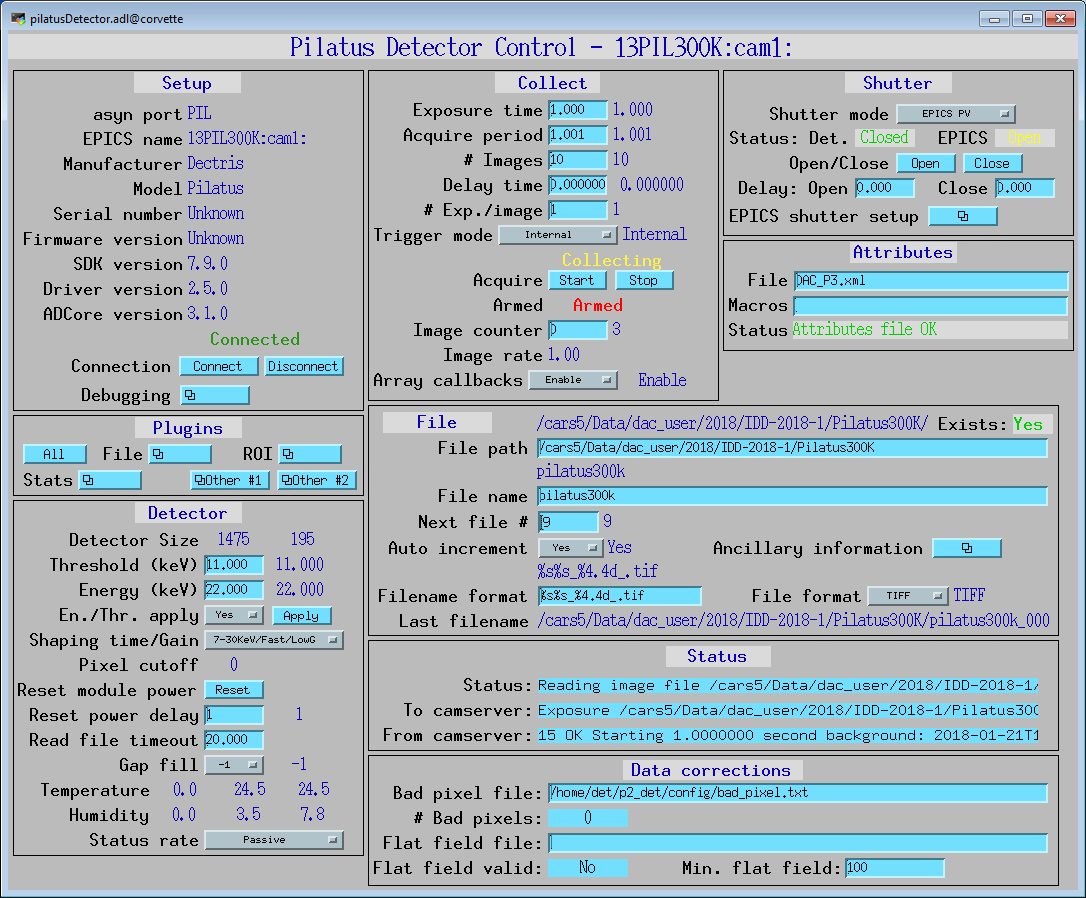
pilatusDetector.adl is the main screen used to control the Pilatus
driver.
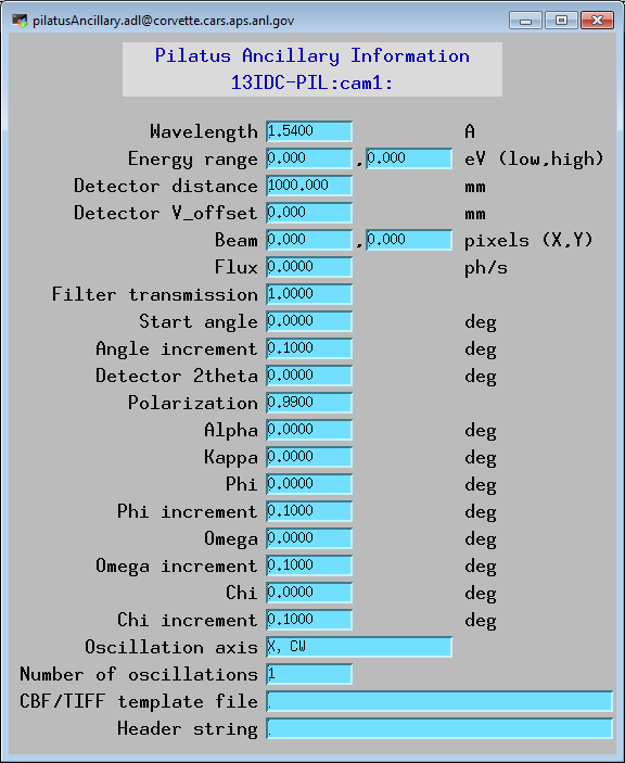
pilatusAncillary.adl is the screen used to control define the metadata
that will be written to the Pilatus data file.
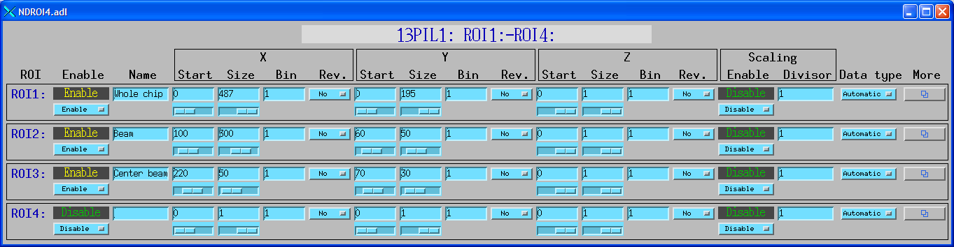
NDROI4.adl is used to define the ROIs. In this example there are 3
valid ROIs defined. ROI 1 is the entire detector, ROI 2 is a 300x50 rectangle starting
at [100,60], and ROI 3 is a 50x30 rectangle starting at [220,70].
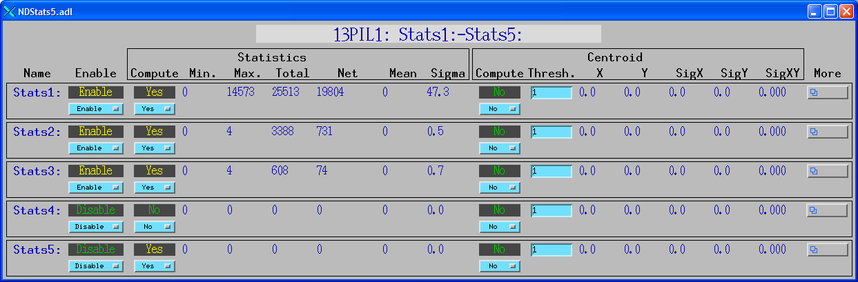
NDStats5.adl is used to display the statistics in the ROIs defined
above.
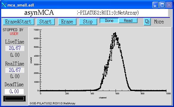
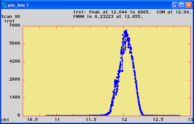
mca.adl or mca_small.adl can be used to plot the net or total counts
in an ROI when NImages>1. In this example the plot is the net counts in ROI 1 as
the diffractometer chi was scanned +- 1 degree with 1000 points at .02 seconds/point.
This was done with the SPEC command
lup chi -1 1 1000 .02
using trajectory scanning on a Newport kappa diffractometer. This was a compound motor scan with the Newport XPS putting out pulses every .02 seconds. These pulses triggered the Pilatus in External Enable mode. The Pilatus driver read each TIFF file as it was created and updated this plot every 0.2 seconds. The total time to collect this scan with 1000 images was 20.8 seconds.
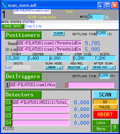
scan_more.adl is used to define a scan. In this example the sscan record
is set up to scan the ThresholdEnergy PV and to collect the total counts in ROI2,
which was defined to include the entire detector.
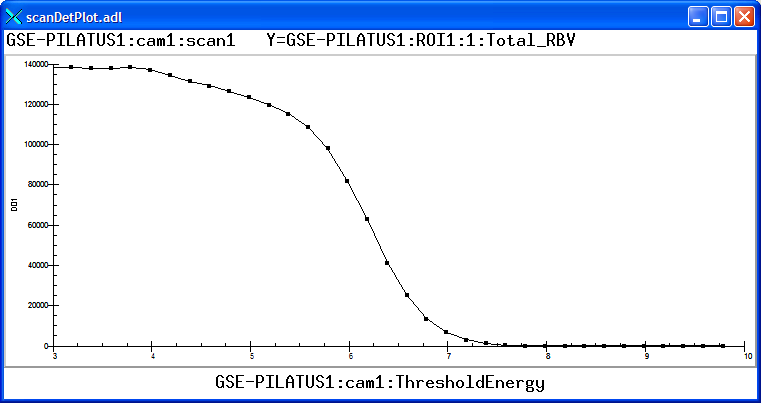
scanDetPlot.adl is used to plot the results of a scan after it is complete.
In this example the total counts in ROI 1 are plotted as a function of the ThresholdEnergy
as it was scanned from 3000 to 10000 eV in 250 eV steps. The source was Fe55, and
the cut-off is at 6 keV, as expected for the Mn Ka and Mn Kb x-rays that this source
produces.
asynRecord.adl is used to control the debugging information printed
by the asyn TCP/IP driver for camserver (asynTraceIODriver).
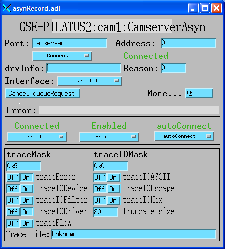
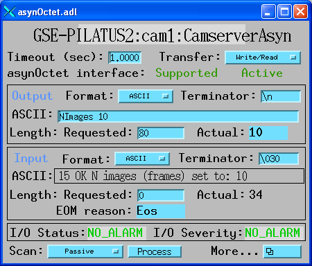
asynOctet.adl can be used to send any command to camserver and display
the response. It can be loaded from the More menu in asynRecord.adl above.
At the GSECARS beamlines (13-ID-C and 13-BM-C) at the APS we use SPEC to control our Newport diffractometers. We have added and modified SPEC macros to use the pilatusDetector areaDetector driver to treat the Pilatus detector as a SPEC counter. This works in both traditional step-scanning mode, as well as in trajectory scanning mode. Here are some snippets from the SPEC macros for the Pilatus. We can supply the source files on request.
  # need some more globals (kludge)
global    PILATUS_ROI_PV
global    PILATUS_ROI_ARRAY_PV
global    PILATUS_ROI_ARRAY_START_PV
global    PILATUS_ROI_ARRAY_NUSE_PV
global    PILATUS_ROI_ARRAY_ACQ_PV
global    PILATUS_IMGPATH_PV
global    PILATUS_FNAME_PV
global    PILATUS_FILENUMBER_PV
global    PILATUS_FILEFORMAT_PV
global    PILATUS_EXPSRTM_PV
global    PILATUS_NFRAME_PV
global    PILATUS_EXPPRD_PV
global    PILATUS_NEXPFRM_PV
global    PILATUS_ACQ_PV
global    PILATUS_ARMED_PV
global    PILATUS_ABORT_PV
global    PILATUS_ACQMODE_PV
global    PILATUS_READOUT_TIME

global    PILATUS_ROI_0_MinX_PV
global    PILATUS_ROI_0_SizeX_PV
global    PILATUS_ROI_0_MinY_PV
global    PILATUS_ROI_0_SizeY_PV


###############################################################
def _setup_img '{
...
     # PILATUS_PREFIX detector name i.e. (GSE-PILATUS1:)
     if ( PILATUS_PREFIX == "") PILATUS_PREFIX = "GSE-PILATUS1:"
     PILATUS_PREFIX = getsval("Enter PILATUS detector name i.e. GSE-PILATUS1:",PILATUS_PREFIX)

     # PILATUS_DET_PREFIX is the pv used by areaDetector to identify a specific detector.
     # When only one detector is used it is usally (cam1:)
     if ( PILATUS_DET_PREFIX == "") PILATUS_DET_PREFIX = "cam1:"
     PILATUS_DET_PREFIX = getsval("Enter PILATUS specific detector name i.e. cam1:",PILATUS_DET_PREFIX)

     # PILATUS_ROI_PREFIX is the pv used by areaDetector to identify a specific a ROI plugin.
     # When only one ROI plugin is used it is usally (ROI1:)
     if ( PILATUS_ROI_PREFIX == "") PILATUS_DET_PREFIX = "ROI1:"
     PILATUS_ROI_PREFIX = getsval("Enter PILATUS ROI plugin name i.e. ROI1:",PILATUS_ROI_PREFIX)

     if (PILATUS_MOUNT == "") PILATUS_MOUNT = "cars5/Data"
     PILATUS_MOUNT = getsval("Enter mount point relative to camserver home directory",PILATUS_MOUNT)
     if (PILATUS_SPEC_MOUNT == "") PILATUS_SPEC_MOUNT = "cars5/Data"
     PILATUS_SPEC_MOUNT = getsval("Enter mount point relative to spec home directory",PILATUS_SPEC_MOUNT)
...
     PILATUS_ROI_PV             = PILATUS_PREFIX PILATUS_ROI_PREFIX "0:Net_RBV"
     PILATUS_ROI_ARRAY_PV       = PILATUS_PREFIX PILATUS_ROI_PREFIX "0:NetArray"
     PILATUS_ROI_ARRAY_START_PV = PILATUS_PREFIX PILATUS_ROI_PREFIX "0:NetArrayEraseStart"
     PILATUS_ROI_ARRAY_NUSE_PV  = PILATUS_PREFIX PILATUS_ROI_PREFIX "0:NetArray.NUSE"
     PILATUS_ROI_ARRAY_ACQ_PV   = PILATUS_PREFIX PILATUS_ROI_PREFIX "0:NetArray.ACQG"
     PILATUS_IMGPATH_PV         = PILATUS_PREFIX PILATUS_DET_PREFIX "FilePath"
     PILATUS_FNAME_PV           = PILATUS_PREFIX PILATUS_DET_PREFIX "FileName"
     PILATUS_FILENUMBER_PV      = PILATUS_PREFIX PILATUS_DET_PREFIX "FileNumber"
     PILATUS_FILEFORMAT_PV      = PILATUS_PREFIX PILATUS_DET_PREFIX "FileTemplate"
     PILATUS_EXPSRTM_PV         = PILATUS_PREFIX PILATUS_DET_PREFIX "AcquireTime"
     PILATUS_NFRAME_PV          = PILATUS_PREFIX PILATUS_DET_PREFIX "NumImages"
     PILATUS_EXPPRD_PV          = PILATUS_PREFIX PILATUS_DET_PREFIX "AcquirePeriod"
     PILATUS_NEXPFRM_PV         = PILATUS_PREFIX PILATUS_DET_PREFIX "NumExposures"
     PILATUS_ACQ_PV             = PILATUS_PREFIX PILATUS_DET_PREFIX "Acquire"
     PILATUS_ARMED_PV           = PILATUS_PREFIX PILATUS_DET_PREFIX "Armed"
     PILATUS_ABORT_PV           = PILATUS_PREFIX PILATUS_DET_PREFIX "Acquire"
     PILATUS_ACQMODE_PV         = PILATUS_PREFIX PILATUS_DET_PREFIX "TriggerMode"
     PILATUS_THRESHOLD_PV       = PILATUS_PREFIX PILATUS_DET_PREFIX "ThresholdEnergy"
     PILATUS_ROI_0_MinX_PV      = PILATUS_PREFIX PILATUS_ROI_PREFIX "0:MinX"
     PILATUS_ROI_0_SizeX_PV     = PILATUS_PREFIX PILATUS_ROI_PREFIX "0:SizeX"
     PILATUS_ROI_0_MinY_PV      = PILATUS_PREFIX PILATUS_ROI_PREFIX "0:MinY"
     PILATUS_ROI_0_SizeY_PV     = PILATUS_PREFIX PILATUS_ROI_PREFIX "0:SizeY"
     PILATUS_ROI_0_BgdWidth_PV  = PILATUS_PREFIX PILATUS_ROI_PREFIX "0:BgdWidth"
...

def epics_pilatus_count '{
...
     # Call macro that creates and set the Pilatus path and filename
     img_full_filename

     # Setup exposure time, collection mode and number of frames
     epics_put(PILATUS_FILENUMBER_PV,NPTS, 1)
     epics_put(PILATUS_NFRAME_PV, 1, 1)
     epics_put(PILATUS_ACQMODE_PV,0, 1)  # Internal trigger
     epics_put(PILATUS_EXPSRTM_PV,cnt_time_val, 1)
     epics_put(PILATUS_NEXPFRM_PV, 1, 1)

...
     # hit the triggers
     epics_put(PILATUS_ACQ_PV,1)

     epics_put(sc_cnt_pv,1)

     # wait for scaler and Pilatus AQG to finish
     status     = 1
     sc_done    = FALSE
     img_done   = FALSE
     data_done  = FALSE
     while(status){
         # is the scalar done
        if (epics_get(sc_cnt_pv)=="Done"){
             sc_done = TRUE;
             #p "scaler done"
        }

        # is the pilatus done
        if (epics_get(PILATUS_ACQ_PV) == "Done"){
            img_done = TRUE;
            #p "image collection done"
        }

        if( (sc_done==TRUE) && (img_done==TRUE)) break;
        sleep(0.01)
     }


     # use the get_counts routine to read the scalers
     # note get_counts also calls user_getcounts
     # thats where the rois get read.
     get_counts
}'


def user_getcounts '{
...
    # using image_count routine
    } else if ( EPICS_COUNT == 4 ) {
        S[iroi] = 0
        S[iroi] = epics_get(PILATUS_ROI_PV)
The following measurements were done to demonstrate the performance that can be obtained with the areaDetector Pilatus driver.
lup chi -1 1 1000 .02
This tells SPEC to do a relative scan of the chi axis from -2 degrees to +2 degrees
with 1000 points at .015 seconds/point. On our kappa diffractometer this entails
a coordinated motion of the phi, kappa and omega axes. The EPICS trajectory scanning
software downloads the non-linear trajectory that SPEC computes into the XPS controller,
which executes it. As the motors are moving the XPS outputs synchronization pulses
at the period of the collection time, .020 seconds in this case. These pulses are
used as the external trigger to the Pilatus. The time to execute this scan should
be 20.0 seconds. The actual time was 20.8 seconds, measured using camonitor on the
Acquire PV. Again, this includes the time for camserver to save all 1000 images
to disk (366 MB), and for the Pilatus driver to read each file, correct the bad
pixels and flat field, compute the ROIs, and post the ROIs to EPICS. It also posted
all of the images to EPICS. The total additional time was less than 0.8 seconds
for all 1000 images. As soon as the acquisition was complete SPEC plotted the net
counts in the first ROI (containing the Bragg peak) as follows:
For comparison this identical scan was executed in traditional step-scanning mode, where the motors stopped at each point in the scan. The Pilatus was run in Internal mode with NumImages=1. The total time for the scan was 870 seconds (more than 14 minutes), compared to 20.8 seconds in trajectory mode. Most of this overhead is the settling time for the motors, with only a small fraction due to the Pilatus single-exposure mode. The trajectory scanning mode is thus more than 50 times faster to execute the identical SPEC scan.
The Pilatus supports 3 types of external triggering. In External Trigger mode (the camserver ExtTrigger command) the Pilatus uses the programmed values of AcquireTime, AcquirePeriod, NImages and NExposures. It waits for a single external trigger, then waits for Delay seconds and then collects the entire sequence. It is very similar to Internal mode with NImages>1, except that it waits for a trigger to begin collecting the sequence.
In External Enable mode (the camserver ExtEnable command) the Pilatus uses the external signal to control acquisition. Only NImages and NExposures are used, AcquireTime and AcquirePeriod are not used. When the signal is high the detector counts, and on the transition to low it begins its readout.
In External MultiTrigger Mode (the camserver ExtMTrigger command) the Pilatus uses the programmed AcquireTime, in addition to NImages and NExposures. Each external trigger pulse causes the Pilatus to collect one image at the programmed exposure time. This mode works well with a trigger source like the Newport motor controllers or the SIS380x multichannel scaler, that put out a short trigger pulse for each image. One only needs to take care that the time between external trigger pulses is at least 4msec longer than the programmed exposure time, to allow time for the detector to read out before the next trigger pulse arrives.
When using the External Enable mode, we use an inexpensive analog pulse generator to convert the trigger pulses from the MM4005 and XPS to a form suitable for External Enable mode with the Pilatus. This is the solution we have developed that seems to be reliable:
The Tenma TGP110 seems to be currently called a Tenma 72-6860, and lists for about $350 new at Newark.
When we were initially testing the Pilatus in the lab, we had many errors in External Enable mode, where it did not seem to be seeing the external pulses. camserver would get DMA timeouts, and need to be restarted. Dectris said these were happening because the cables on our detector are longer than normal, and the voltage drop from the power supply to the detector was leading to marginal voltage values. They suggested shortening the cables or increasing the supply voltage slightly. When moving the detector to the hutch these problems initially went away. However, they then recurred, and we fixed the problem by increasing the power supply voltage from 4.4 to 4.7 volts at the detector.
Dectris has since informed me that they have increased the power supply voltage on all new Pilatus systems, so this should no longer be an issue.
The following are some current restrictions of the areaDetector Pilatus driver: