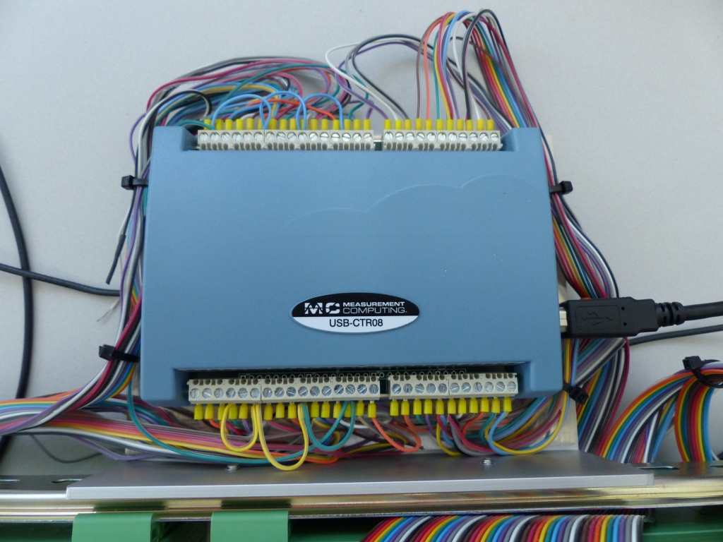
Photo of USB-CTR08
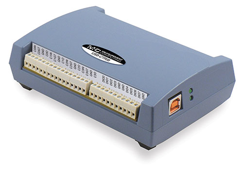
This is an EPICS driver for the USB-CTR04 and USB-CTR08 counter/timer module from Measurement Computing The driver is written in C++, and consists of a class that inherits from asynPortDriver, which is part of the EPICS asyn module.
This module has the following features:
The following lines are needed in the EPICS startup script for the USBCTR.
# This line is for Linux only
cbAddBoard("USB-CTR", "")

## Set the minimum sleep time to 1 ms
asynSetMinTimerPeriod(0.001)

## Configure port driver
# USBCTRConfig(portName,       # The name to give to this asyn port driver
#              boardNum,       # The number of this board assigned by the Measurement Computing Instacal program
#              maxTimePoints)  # Maximum number of time points for MCS
USBCTRConfig("$(PORT)", 0, 2048, .01)

#asynSetTraceMask($(PORT), 0, TRACE_ERROR|TRACE_FLOW|TRACEIO_DRIVER)

dbLoadTemplate("USBCTR.substitutions")

# This loads the scaler record and supporting records
dbLoadRecords("$(STD)/stdApp/Db/scaler.db", "P=USBCTR:, S=scaler1, DTYP=Asyn Scaler, OUT=@asyn(USBCTR), FREQ=10000000")

# This database provides the support for the MCS functions
dbLoadRecords("$(MEASCOMP)/measCompApp/Db/measCompMCS.template", "P=$(PREFIX), PORT=$(PORT)")

# Load either MCA or waveform records below
# The number of records loaded must be the same as MAX_COUNTERS defined above

# Load the MCA records
#dbLoadRecords("$(MCA)/mcaApp/Db/simple_mca.db", "P=$(PREFIX), M=$(RNAME)1,  DTYP=asynMCA, INP=@asyn($(PORT) 0),  PREC=3, CHANS=$(MAX_POINTS)")
#dbLoadRecords("$(MCA)/mcaApp/Db/simple_mca.db", "P=$(PREFIX), M=$(RNAME)2,  DTYP=asynMCA, INP=@asyn($(PORT) 1),  PREC=3, CHANS=$(MAX_POINTS)")
#dbLoadRecords("$(MCA)/mcaApp/Db/simple_mca.db", "P=$(PREFIX), M=$(RNAME)3,  DTYP=asynMCA, INP=@asyn($(PORT) 2),  PREC=3, CHANS=$(MAX_POINTS)")
#dbLoadRecords("$(MCA)/mcaApp/Db/simple_mca.db", "P=$(PREFIX), M=$(RNAME)4,  DTYP=asynMCA, INP=@asyn($(PORT) 3),  PREC=3, CHANS=$(MAX_POINTS)")
#dbLoadRecords("$(MCA)/mcaApp/Db/simple_mca.db", "P=$(PREFIX), M=$(RNAME)5,  DTYP=asynMCA, INP=@asyn($(PORT) 4),  PREC=3, CHANS=$(MAX_POINTS)")
#dbLoadRecords("$(MCA)/mcaApp/Db/simple_mca.db", "P=$(PREFIX), M=$(RNAME)6,  DTYP=asynMCA, INP=@asyn($(PORT) 5),  PREC=3, CHANS=$(MAX_POINTS)")
#dbLoadRecords("$(MCA)/mcaApp/Db/simple_mca.db", "P=$(PREFIX), M=$(RNAME)7,  DTYP=asynMCA, INP=@asyn($(PORT) 6),  PREC=3, CHANS=$(MAX_POINTS)")
#dbLoadRecords("$(MCA)/mcaApp/Db/simple_mca.db", "P=$(PREFIX), M=$(RNAME)8,  DTYP=asynMCA, INP=@asyn($(PORT) 7),  PREC=3, CHANS=$(MAX_POINTS)")
#dbLoadRecords("$(MCA)/mcaApp/Db/simple_mca.db", "P=$(PREFIX), M=$(RNAME)9,  DTYP=asynMCA, INP=@asyn($(PORT) 8),  PREC=3, CHANS=$(MAX_POINTS)")

# This loads the waveform records
dbLoadRecords("$(MCA)/mcaApp/Db/SIS38XX_waveform.template", "P=$(PREFIX), R=$(RNAME)1,  INP=@asyn($(PORT) 0),  CHANS=$(MAX_POINTS)")
dbLoadRecords("$(MCA)/mcaApp/Db/SIS38XX_waveform.template", "P=$(PREFIX), R=$(RNAME)2,  INP=@asyn($(PORT) 1),  CHANS=$(MAX_POINTS)")
dbLoadRecords("$(MCA)/mcaApp/Db/SIS38XX_waveform.template", "P=$(PREFIX), R=$(RNAME)3,  INP=@asyn($(PORT) 2),  CHANS=$(MAX_POINTS)")
dbLoadRecords("$(MCA)/mcaApp/Db/SIS38XX_waveform.template", "P=$(PREFIX), R=$(RNAME)4,  INP=@asyn($(PORT) 3),  CHANS=$(MAX_POINTS)")
dbLoadRecords("$(MCA)/mcaApp/Db/SIS38XX_waveform.template", "P=$(PREFIX), R=$(RNAME)5,  INP=@asyn($(PORT) 4),  CHANS=$(MAX_POINTS)")
dbLoadRecords("$(MCA)/mcaApp/Db/SIS38XX_waveform.template", "P=$(PREFIX), R=$(RNAME)6,  INP=@asyn($(PORT) 5),  CHANS=$(MAX_POINTS)")
dbLoadRecords("$(MCA)/mcaApp/Db/SIS38XX_waveform.template", "P=$(PREFIX), R=$(RNAME)7,  INP=@asyn($(PORT) 6),  CHANS=$(MAX_POINTS)")
dbLoadRecords("$(MCA)/mcaApp/Db/SIS38XX_waveform.template", "P=$(PREFIX), R=$(RNAME)8,  INP=@asyn($(PORT) 7),  CHANS=$(MAX_POINTS)")
dbLoadRecords("$(MCA)/mcaApp/Db/SIS38XX_waveform.template", "P=$(PREFIX), R=$(RNAME)9,  INP=@asyn($(PORT) 8),  CHANS=$(MAX_POINTS)")

asynSetTraceIOMask($(PORT),0,2)
#asynSetTraceFile("$(PORT)",0,"$(MODEL).out")

< save_restore.cmd
save_restoreSet_status_prefix($(PREFIX))
dbLoadRecords("$(AUTOSAVE)/asApp/Db/save_restoreStatus.db", "P=$(PREFIX)")

iocInit

seq(USBCTR_SNL, "P=$(PREFIX), R=$(RNAME), NUM_COUNTERS=$(MAX_COUNTERS), FIELD=$(FIELD)")
create_monitor_set("auto_settings.req",30)
The measComp module comes with an example iocBoot/iocUSBCTR directory that contains and example startup script and example substitution files.
The following tables list the database template files that are used with the USB-CTR04/08.
| EPICS record name | EPICS record type | asyn interface | drvInfo string | Description |
|---|---|---|---|---|
| measCompBinaryIn.template. This database is loaded once for each of the 8 binary I/O bits. | ||||
| $(P)$(R) | bi | asynUInt32Digital | DIGITAL_INPUT | Digital input value. The MASK parameter in the INP link defines which bit is used. The binary inputs are polled by the driver poller thread, so these records should have SCAN="I/O Intr". |
| measCompLongIn.template. This database is loaded once for each module. | ||||
| $(P)$(R) | longin | asynUInt32Digital | DIGITAL_INPUT | Digital input value as a word, rather than individual bits. The MASK parameter in the INP link defines which bits are used. The binary inputs are polled by the driver poller thread, so this record should have SCAN="I/O Intr". |
| measCompBinaryOut.template. This database is loaded once for each of the 8 binary I/O bits. | ||||
| $(P)$(R) | bo | asynUInt32Digital | DIGITAL_OUTPUT | Digital output value. The MASK parameter in the INP link defines which bit is used. |
| $(P)$(R)_RBV | bi | asynUInt32Digital | DIGITAL_OUTPUT | Digital output value readback. The MASK parameter in the INP link defines which bit is used. |
| measCompLongOut.template. This database is loaded once for each module. | ||||
| $(P)$(R) | longout | asynUInt32Digital | DIGITAL_OUTPUT | Digital output value as a word, rather than individual bits. The MASK parameter in the INP link defines which bits are used. |
| $(P)$(R)_RBV | longin | asynUInt32Digital | DIGITAL_OUTPUT | Digital output value readback as a word, rather than individual bits. The MASK parameter in the INP link defines which bits are used. |
| measCompBinaryDir.template. This database is loaded once for each of the 8 binary I/O bits. | ||||
| $(P)$(R) | bo | asynUInt32Digital | DIGITAL_DIRECTION | Direction of this I/O line, "In" (0) or "Out" (1). The MASK parameter in the INP link defines which bit is used. |
| measCompPulseGen.template. This database is loaded once for each of the 4 pulse generators. | ||||
| EPICS record name | EPICS record type | asyn interface | drvInfo string | Description |
|---|---|---|---|---|
| $(P)$(R)Run | bo | asynUInt32 | PULSE_RUN | "Run" (1) starts the pulse generator, "Stop" (0) stops the pulse generator. Note that ideally this record should go back to 0 when the pulse generator is done, if it is outputting a finite number of pulses (see Count record). But unfortunately the Measurement Computing library does not have a way to query the status of the timer to see if it is done, so this is not possible. |
|
$(P)$(R)Period $(P)$(R)Period_RBV |
ao ai |
asynFloat64 | PULSE_PERIOD | Pulse period, in seconds. The time between pulses can be defined either with the Period or with the Frequency; whenever one record is changed the other is updated with the new calculated value. The minimum value is 20.83 ns (48 MHz) and the maximum value is 45.4 seconds. Period_RBV is the actual (readback) value which may differ from the requested value because the 96 MHz system clock constrains the period to be an integer multiple of 10.4166 ns. |
|
$(P)$(R)Frequency
$(P)$(R)Frequency_RBV |
ao
calc |
N.A. | N.A. | Pulse frequency, in seconds. The Frequency calculates a new value of the Period, and sends the period value to the driver. The Frequency_RBV is calculated from the Period_RBV value. |
|
$(P)$(R)Width
$(P)$(R)Width_RBV |
ao
ai |
asynFloat64 | PULSE_WIDTH | Pulse width, in seconds. The allowed range is 10.42 ns to (Period-10.42 ns). Width_RBV is the actual (readback) value which may differ from the requested value because the 96 MHz system clock constrains the width to be an integer multiple of 10.4166 ns. |
|
$(P)$(R)Delay
$(P)$(R)Delay_RBV |
ao
ai |
asynFloat64 | PULSE_DELAY | Initial pulse delay in seconds after Run is set to 1. Delay_RBV is the actual (readback) value which may differ from the requested value because the 96 MHz system clock constrains the width to be an integer multiple of 10.4166 ns. |
| $(P)$(R)Count | longout | asynInt32 | PULSE_COUNT | Number of pulses to output. If the Count is 0 then the pulse generator runs continuously until Run is set to 0. |
| $(P)$(R)IdleState | bo | asynInt32 | PULSE_IDLE_STATE | The idle state of the pulse output line, "Low" (0) or "High" (1). This determines the polarity of the pulse, i.e. positive going or negative going. |
The USBCTR driver provides support for the EPICS scaler record via the devScalerAsyn.c device support in the synApps std module. It supports up to 8 channels. The following wiring connections must be made in order for counters 1-8 to be stopped by counter 0, as is normally desired.
The .PR1 preset is performed in hardware via the Counter 0 Output and Counters 1-7 gates. Counters 1-7 can also be set as preset counters, and the scaler record will stop counting when any of these preset values (.PR2-.PR8) are exceeded. However, unlike the .PR1 preset, these presets are done in software in the driver polling routine. The device sends readings at 100 Hz, and whenever a preset is exceeded counting is stopped. Each of the counters will have counted for exactly the same amount of time, but the actual count time could be up to 0.01 seconds longer than the time when the preset was reached.
Counter 0 is normally used as the preset counter, and is connected to a fixed frequency source. Any of the on-board pulse generators can be used to provide this frequency source, for example. It is important to set the scaler record .FREQ field to be the value of the Frequency_RBV of the pulse generator (the actual frequency) and not the Frequency field (the requested frequency) since these can differ, particularly at frequencies >1 MHz.
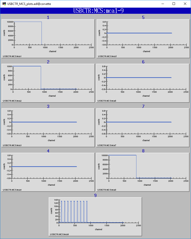
The USBCTR driver provides multi-channel scaler support very similar to the SIS3820 driver in the synApps mca module. The support has the following properties:
| measCompMCS.template. This database is loaded once per module. | ||||
| EPICS record name | EPICS record type | asyn interface | drvInfo string | Description |
|---|---|---|---|---|
| $(P)$(R)SNL_Connected | bi | N.A. | N.A. | This record is 1 ("Connected") if all PVs have connected in the USBCTR_SNL State Notation Language program. |
| $(P)$(R)EraseAll | bo | asynInt32 | MCA_ERASE | Erases the MCS data, setting the arrays and the elapsed times to 0. |
| $(P)$(R)EraseStart | bo | asynInt32 | MCA_ERASE | Erases the MCS data and then starts MCS acquisition by forward linking to StartAll. |
| $(P)$(R)StartAll | bo | asynInt32 | MCA_START_ACQUIRE | Starts MCS acquisition. |
| $(P)$(R)Acquiring | busy | N.A. | N.A. | Busy record is 1 ("Acquiring") when MCS is acquiring and 0 ("Done") when done.. |
| $(P)$(R)StopAll | bo | asynInt32 | MCA_STOP_ACQUIRE | Stops MCS acquisition. |
| $(P)$(R)PresetReal | ao | asynFloat64 | MCA_PRESET_REAL | Preset real time. If non-zero acquisition will stop after this time. |
| $(P)$(R)ElapsedReal | ai | asynFloat64 | MCA_ELAPSED_REAL | Elapsed real time. |
| $(P)$(R)ReadAll | bo | N.A | N.A. | Forces a read of all of the array data. This is done by the SNL program. |
| $(P)$(R)NuseAll | longout | asynInt32 | MCA_NUM_CHANNELS | The number of time points to acquire. |
| $(P)$(R)CurrentChannel | longin | asynInt32 | MCS_CURRENT_POINT | The current time point in the acquisition. |
| $(P)$(R)Dwell | ao | asynFloat64 | MCA_DWELL_TIME | The dwell time per time point in internal channel advance mode. |
| $(P)$(R)ChannelAdvance | bo | asynInt32 | MCA_CH_ADV_SOURCE | The channel advance source. 0="Internal" uses DWELL record, 1="External" uses External Clock Input on USB-CTR module. |
| $(P)$(R)Prescale | bo | asynInt32 | MCA_PRESCALE | The prescale factor for the external channel advance source. To use Prescale the external clock must be input to the counter channel selected by PrescaleCounter, and the output of the PrescaleCounter counter channel must be connected to the External Clock Input. Note that due to hardware limitations Prescale must be > 1. For no prescaling the external channel advance source must be connected directly to the External Clock Input. |
| $(P)$(R))MCSCounterNEnable (N=1-8) | bo | asynInt32 | N.A. | Enable counter N in MCS mode. Choices are "No" (0) and "Yes" (1). |
| $(P)$(R))MCSDIOEnable | bo | asynInt32 | N.A. | Enable collecting digital I/O word in MCS mode. Choices are "No" (0) and "Yes" (1). |
| $(P)$(R)PrescaleCounter | mbbo | asynInt32 | MCS_PRESCALE_COUNTER | The counter channel to use for prescaling the external channel advance in MCS mode. 0="CNTR0" ... 7="CNTR7". |
| $(P)$(R)Point0Action | mbbo | asynInt32 | MCS_POINT0_ACTION |
Controls how the first time point in the MCS scan is handled. The USB-CTR always
reads the current scaler counts as soon as MCS acquisition begins, rather than after
the first channel advance occurs. This record selects one of the following 3 modes:
|
| $(P)$(R)TrigMode | mbbo | asynInt32 | TRIGGER_MODE |
Controls trigger of the MCS scan. Choices are:
|
| $(P)$(R)MaxChannels | longin | asynInt32 | MCS_MAX_POINTS | The maximum number of points in MCS arrays. This is determined by the value of the MAX_POINTS macro parameter when loading the MCA or waveform records. |
| $(P)$(R)Model | mbbi | asynInt32 | MODEL | The model number of the counter module. 0="USB-CRT08", 1="USB-CTR04". |
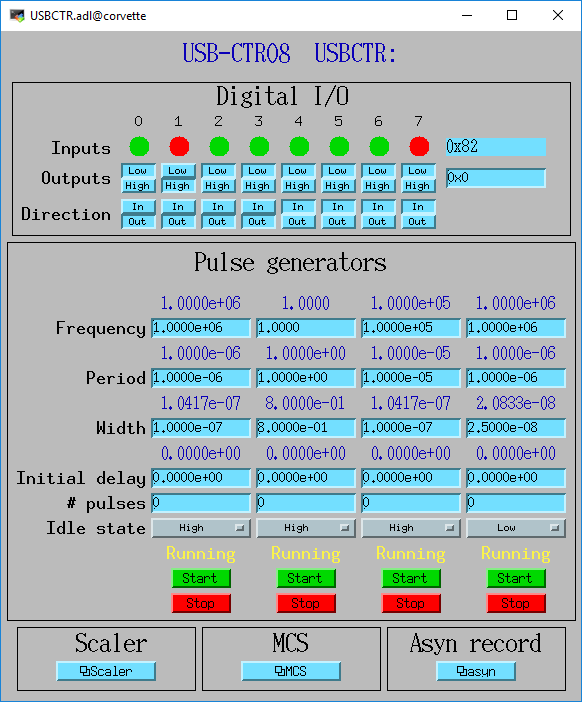
The following is the main medm screen for controlling the USB-CTR04/08.
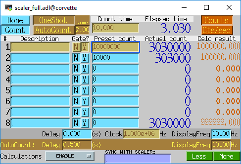
The following is the medm screen for the EPICS scaler record using the USB-CTR04/08.
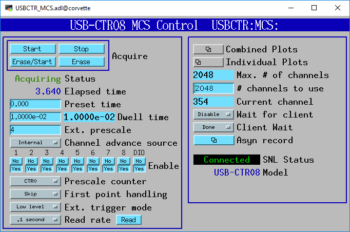
The following is the medm screen for controlling the MCS mode of the USB-CTR04/08.
The following photos show the BCDA BC-020 LEMO breakout panels wired to the USB-CTR08. A BC-020 with a BC-087 daughter card (left) is used for the 8 counter signals, and a BC-020 with wire-wrapping (right) is used for digital I/O, timer output, clock I/O, etc. .
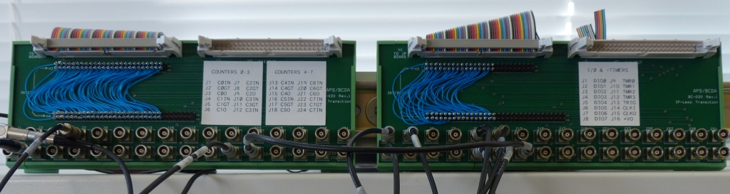
      Digital I/O and other signals using wire-wrap connections

50-pin ribbon      USB-1608GX      BC-020       EPICS Function
connector pin    screw terminal   connector
 1                DIO0               J1         Digital I/O bit 0
 2                 GND               J1 shell   Ground
 3                DIO1               J2         Digital I/O bit 1
 4                 GND               J2 shell   Ground
 5                DIO2               J3         Digital I/O bit 2
 6                 GND               J3 shell   Ground
 7                DIO3               J4         Digital I/O bit 3
 8                 GND               J4 shell   Ground
 9                DIO4               J5         Digital I/O bit 4
10                 GND               J5 shell   Ground
11                DIO5               J6         Digital I/O bit 5
12                 GND               J6 shell   Ground
13                DIO6               J7         Digital I/O bit 6
14                 GND               J7 shell   Ground
15                DIO7               J8         Digital I/O bit 7
16                 GND               J8 shell   Ground
17                TMR0               J9         Pulse generator 0 output
18                 GND               J9 shell   Ground
19                TMR1              J10         Pulse generator 1 output
20                 GND              J10 shell   Ground
21                TMR2              J11         Pulse generator 2 output
22                 GND              J11 shell   Ground
23                TMR3              J12         Pulse generator 3 output
24                 GND              J12 shell   Ground
25                TRIG              J13         Trigger input for MCS
26                 GND              J13 shell   Ground
27                CLKI              J14         External channel advance input
28                 GND              J14 shell   Ground
29                CLK0              J15         Clock output
30                 GND              J15 shell   Ground
31                 +VO              J16         +5 volt output
32                 GND              J16 shell   Ground


         Counter I/O using wire-wrap connections

50-pin ribbon      USB-CTR08      BC-020   EPICS Function
connector pin    screw terminal   connector
 1                C0IN               J1         Scaler 1 input
 2                 GND               J1 shell   Ground
 3                C0GT               J2         Scaler 1 gate input
 4                 GND               J2 shell   Ground
 5                 C0O               J3         Scaler 1 output
 6                 GND               J3 shell   Ground
 7                C1IN               J4         Scaler 2 input
 8                 GND               J4 shell   Ground
 9                C1GT               J5         Scaler 2 gate input
10                 GND               J5 shell   Ground
11                 C1O               J6         Scaler 2 output
12                 GND               J6 shell   Ground
13                C2IN               J7         Scaler 3 input
14                 GND               J7 shell   Ground
15                C2GT               J8         Scaler 3 gate input
16                 GND               J8 shell   Ground
17                 C2O               J9         Scaler 3 output
18                 GND               J9 shell   Ground
19                C3IN              J10         Scaler 4 input
20                 GND              J10 shell   Ground
21                C3GT              J11         Scaler 4 gate input
22                 GND              J11 shell   Ground
23                 C4O              J12         Scaler 4 output
24                 GND              J12 shell   Ground
25                C4IN              J13         Scaler 5 input
26                 GND              J14 shell   Ground
27                C4GT              J14         Scaler 5 gate input
28                 GND              J14 shell   Ground
29                 C4O              J15         Scaler 5 output
30                 GND              J15 shell   Ground
31                C5IN              J16         Scaler 6 input
32                 GND              J16 shell   Ground
33                C5GT              J17         Scaler 6 gate input
34                 GND              J17 shell   Ground
35                 C5O              J18         Scaler 6 output
36                 GND              J18 shell   Ground
37                C6IN              J19         Scaler 7 input
38                 GND              J19 shell   Ground
39                C6GT              J20     Scaler 7 gate input
40                 GND              J20 shell   Ground
41                 C6O              J21         Scaler 7 output
42                 GND              J21 shell   Ground
43                C7IN              J22         Scaler 8 input
44                 GND              J22 shell   Ground
45                C7GT              J23         Scaler 8 gate input
46                 GND              J23 shell   Ground
47                 C7O              J24         Scaler 8 output
48                 GND              J24 shell   Ground

In addition to these connections counter 0 output (C0O) was connected to the gate
inputs of counters 1-7 (C1GT - C7GT) at the module screw terminals.
This is cheaper and simpler than using LEMO tees and short cables on the BC-020 module.
The binary input bits are polled at 100 Hz, and the input records have SCAN=I/O Intr. There is thus a worse-case latency of 0.01 seconds in detecting a transition on these bits.
If the scaler record is run under the following conditions:
After each count cycle .S1=32000000 counts exactly, .S2-.S4=32000000 += 1 count. There is thus no cross-talk with all channels running at 32 MHz, and the gate signals are working as designed.
If Pulse Generator 2 is changed to 3.2 MHz, .PR2 is set to 1600000, and .G2 is set to Y, then the scaler is stopped by channel 2 in the software polling routine. In this case it counts for exactly 0.50 seconds. However, if .PR2 is increased to 1600001 then it counts for 0.51 seconds. This corresponds to the worst case error due to the 100 Hz rate at which the scaler values are read. Note that all counters are active for exactly 0.51 seconds, so the counts all accurately reflect this count time. The count time is just slightly longer than requested due to the finite polling interval.
In MCS mode the measured minimum dwell time in both internal and external channel advance mode agrees with the datasheet, i.e. 250 ns * number of active counters. I was not able to measure any dead time between time bins in MCS mode. When sending exactly 8000000 pulses at 8 MHz to channel 0 with a 1 ms internal dwell time the total number of counts in the MCA record was 8000000. This means that no pulses were lost during the 1000 channel advances that happened during this time.