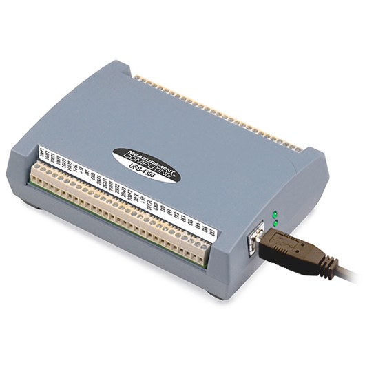
Photo of USB-4303
NOTE: The Measurement Computing USB-4303 is no longer available. It has been replaced with the USB-CTR04/08 which has higher performance and more features.. See the documentation for the EPICS measCompUSBCTR driver for more information.
This is an EPICS driver for the USB-4303 counter/timer module from Measurement Computing The driver should also work with other Measurement Computing devices that are based on the C9513, including the discontinued PCI-CTR10, CIO-CTR10, and PC104-CTR10, but this has not been tested. The driver is written in C++, and consists of a class that inherits from asynPortDriver, which is part of the EPICS asyn module.
This module has the following features:
The CTS9513 chip is extremely flexible. It is beyond the scope of this document to explain the features of the CTS9513. The CTS9513 manual describes all of the chip's features and functions in detail.
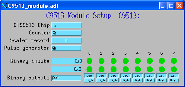
The following is the main medm screen for controlling the USB-4303.
The following lines are needed in the EPICS startup script for the USB-4304 or other CTS9513 board.
## Configure port driver
# C9513Config(portName,   # The name to give to this asyn port driver
#             boardNum,   # The number of this board assigned by the Measurement Computing Instacal program
#             numChips)   # The number of CTS9513 chipts on this board
C9513Config("C9513_1", 0, 2)
dbLoadTemplate("C9513.substitutions")
The measComp module comes with an example iocBoot/iocMeasComp directory that contains example startup scripts and example substitutions files.
| EPICS record name | EPICS record type | asyn interface | drvInfo string | Description |
|---|---|---|---|---|
| measCompBinaryIn.template. This database is loaded once for each binary I/O bit. | ||||
| $(P)$(R) | bi | asynUInt32Digital | DIGITAL_INPUT | Digital input value. The MASK parameter in the INP link defines which bit is used. The binary inputs are polled by the driver poller thread, so these records should have SCAN="I/O Intr". |
| measCompLongIn.template. This database is loaded once for each binary I/O register. | ||||
| $(P)$(R) | longin | asynUInt32Digital | DIGITAL_INPUT | Digital input value as a word, rather than individual bits. The MASK parameter in the INP link defines which bits are used. The binary inputs are polled by the driver poller thread, so this record should have SCAN="I/O Intr". |
| measCompBinaryOut.template. This database is loaded once for each binary I/O bit. | ||||
| $(P)$(R) | bo | asynUInt32Digital | DIGITAL_OUTPUT | Digital output value. The MASK parameter in the INP link defines which bit is used. |
| $(P)$(R)_RBV | bi | asynUInt32Digital | DIGITAL_OUTPUT | Digital output value readback. The MASK parameter in the INP link defines which bit is used. |
| measCompLongOut.template. This database is loaded once for each binary I/O register. | ||||
| $(P)$(R) | longout | asynUInt32Digital | DIGITAL_OUTPUT | Digital output value as a word, rather than individual bits. The MASK parameter in the INP link defines which bits are used. |
| C9513_chip.template. This database is loaded once for each CTS9513 chip, (e.q. 2 instances for USB-4303). | ||||
| EPICS record name | EPICS record type | asyn interface | drvInfo string | Description |
|---|---|---|---|---|
|
$(P)$(R)FOutDivider $(P)$(R)FOutDivider_RBV |
mbbo mbbi |
asynInt32 | FOUT_DIVIDER |
Frequency output divider. Choices are: "1" (1) "2" (2) "..." "16" (0) |
|
$(P)$(R)FOutSource $(P)$(R)FOutSource_RBV |
mbbo mbbi |
asynInt32 | FOUT_SOURCE |
Frequency output source. Choices are: "Prev TC" (Terminal Count on counter N-1) "Input 1" "Input 2" "Input 3" "Input 4" "Input 5" "Gate 1" "Gate 2" "Gate 3" "Gate 4" "Gate 5" "Freq 1 (5 MHz)" "Freq 2 (500 kHz)" "Freq 3 (50 kHz)" "Freq 4 (5 kHz)" "Freq 5 (500 Hz)" |
|
$(P)$(R)Compare1 $(P)$(R)Compare1_RBV |
bo bi |
asynInt32 | COMPARE1 |
Choices are: "Disable" "Enable" |
|
$(P)$(R)Compare2 $(P)$(R)Compare2_RBV |
bo bi |
asynInt32 | COMPARE2 |
Choices are: "Disable" "Enable" |
|
$(P)$(R)TimeOfDay $(P)$(R)TimeOfDay_RBV |
bo bi |
asynInt32 | TIME_OF_DAY |
Choices are: "Disable" "Enable" |
|
$(P)$(R)AlarmReg1 $(P)$(R)AlarmReg1_RBV |
longout longin |
asynInt32 | ALARM_REG1 | Alarm register 1 value. |
|
$(P)$(R)AlarmReg2 $(P)$(R)AlarmReg2_RBV |
longout longin |
asynInt32 | ALARM_REG2 | Alarm register 2 value. |
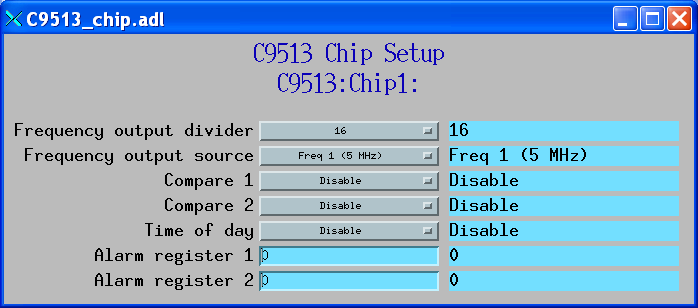
The following is the medm screen for controlling each CTS9513 chip with the records in C9513_chip.template.
| C9513_counter.template. This database is loaded once for CTS9513 counter channel. | ||||
| EPICS record name | EPICS record type | asyn interface | drvInfo string | Description |
|---|---|---|---|---|
|
$(P)$(R)GateControl $(P)$(R)GateControl_RBV |
mbbo mbbi |
asynInt32 | GATE_CONTROL |
Choices are: "No gate" "High TC N-1" (High terminal count on counter N-1) "High level gate N+1" "High level gate N-1" "High level gate N" "Low level gate N" "High edge gate N" "Low edge gate N" |
|
$(P)$(R)CounterEdge $(P)$(R)CounterEdge_RBV |
mbbo mbbi |
asynInt32 | COUNTER_EDGE |
Choices are: "Rising" "Falling" |
|
$(P)$(R)CountSource $(P)$(R)CountSource_RBV |
mbbo mbbi |
asynInt32 | COUNT_SOURCE |
Choices are: "Prev TC" (Terminal Count on counter N-1) "Input 1" "Input 2" "Input 3" "Input 4" "Input 5" "Gate 1" "Gate 2" "Gate 3" "Gate 4" "Gate 5" "Freq 1 (5 MHz)" "Freq 2 (500 kHz)" "Freq 3 (50 kHz)" "Freq 4 (5 kHz)" "Freq 5 (500 Hz)" |
|
$(P)$(R)SpecialGate $(P)$(R)SpecialGate_RBV |
bo bi |
asynInt32 | SPECIAL_GATE |
Choices are: "Disable" "Enable" |
|
$(P)$(R)ReloadSource $(P)$(R)ReloadSource_RBV |
bo bi |
asynInt32 | RELOAD_SOURCE |
Choices are: "Load register" "Load and hold register" |
|
$(P)$(R)RecycleMode $(P)$(R)RecycleMode_RBV |
bo bi |
asynInt32 | RECYCLE_MODE |
Choices are: "One time" "Recycle" |
|
$(P)$(R)BCDMode $(P)$(R)BCDMode_RBV |
bo bi |
asynInt32 | RECYCLE_MODE |
Choices are: "Disable" "Enable" |
|
$(P)$(R)CountDirection $(P)$(R)CountDirection_RBV |
bo bi |
asynInt32 | COUNT_DIRECTION |
Choices are: "Count down" "Count up" |
|
$(P)$(R)OutputControl $(P)$(R)OutputControl_RBV |
mbbo mbbi |
asynInt32 | OUTPUT_CONTROL |
Choices are: "Always low" "High pulse on TC" "Toggle on TC" "Inactive high impedance" "Low pulse on TC" |
|
$(P)$(R)LoadReg $(P)$(R)LoadReg_RBV |
longout longin |
asynInt32 | LOAD_REG | Write/read from the Load Register |
|
$(P)$(R)HoldReg $(P)$(R)HoldReg_RBV |
longout longin |
asynInt32 | HOLD_REG | Write/read from the Load and Hold Register |
|
$(P)$(R)PollCounter $(P)$(R)PollCounter_RBV |
bo bi |
asynInt32 | POLL_COUNTER |
Poll this counter in the polling thread. Choices are: "No" "Yes" |
| $(P)$(R)CounterValue | longin | asynInt32 | COUNTER_VALUE | The contents of the counter. |
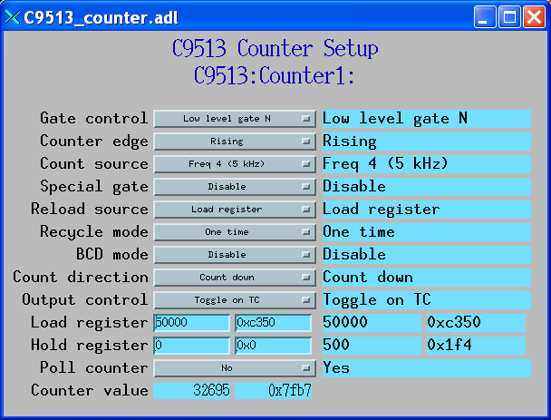
The following is the medm screen for controlling each counter with the records in C9513_counter.template.
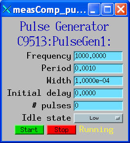
| measCompPulseGen.template. This database is loaded once for each pulse counter (e.g. 10 times for USB-4303). | ||||
| EPICS record name | EPICS record type | asyn interface | drvInfo string | Description |
|---|---|---|---|---|
| $(P)$(R)Run | bo | asynUInt32 | PULSE_RUN | "Run" (1) starts the pulse generator, "Stop" (0) stops the pulse generator. Note that ideally this record should go back to 0 when the pulse generator is done, if it is outputting a finite number of pulses (see Count record). But unfortunately the Measurement Computing library does not have a way to query the status of the timer to see if it is done, so this is not possible. |
| $(P)$(R)Period | ao | asynFloat64 | PULSE_PERIOD | Pulse period, in seconds. The time between pulses can be defined either with the Period or with the Frequency; whenever one record is changed the other is updated with the new calculated value. |
| $(P)$(R)Frequency | ao | N.A. | N.A. | Pulse frequency, in seconds. The Frequency calculates a new value of the Period, and sends the period value to the driver. |
| $(P)$(R)Width | ao | asynFloat64 | PULSE_WIDTH | Pulse width, in seconds. The allowed value is 1 to 65535 times the period of the currently selected frequency source. |
| $(P)$(R)Delay | ao | asynFloat64 | PULSE_DELAY | Initial pulse delay in seconds after Run is set to 1. NOTE: this is currently not implemented for CTS9513 counters. |
| $(P)$(R)Count | longout | asynInt32 | PULSE_COUNT | Number of pulses to output. If the Count is 0 then the pulse generator runs continuously until Run is set to 0. NOTE: this is currently not implemented for CTS9513 counters. |
| $(P)$(R)IdleState | bo | asynInt32 | PULSE_IDLE_STATE | The idle state of the pulse output line, "Low" (0) or "High" (1). This determines the polarity of the pulse, i.e. positive going or negative going. |
When the pulse generator is started it configures the corresponding counter. This may change the readback (_RBV) value of the counter functions, but will not change the values of the output records.
The pulse generator implementation in the driver is very simple, and does not support the Count, Delay or IdleState records. It is not possible to support these functions on all 5 counter channels of a CTS9513 chip. It may be possible to implement some of these functions by combining counter channels together to have fewer pulse generators with more features, but this has not been tested.
The following is the medm screen for controlling each pulse generator with the records in measCompPulseGen.template.
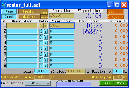
The driver supports the EPICS scaler record. The are some limitations to the support.
When the scaler record is started it configures each of the 10 counters so that they work together. This may change the readback (_RBV) value of the counter functions, but will not change the values of the output records.
The following is the medm screen for controlling the EPICS scaler record.
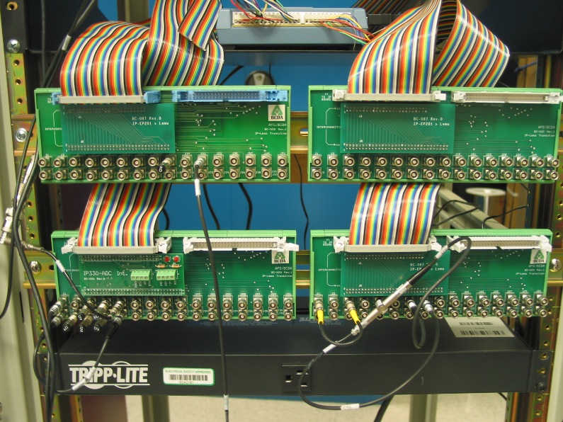
The following photo shows the BCDA BC-020 LEMO breakout panels wired to the USB-4303. These are the upper 2 BC-020 panels in this photo.
           BC-020 #1 using BC-087 daughter card

50-pin ribbon    USB-4303         BC-020    EPICS Function
connector pin   screw terminal   connector
 1                 DO0               J1     Digital output bit 0
 2                 DO1               J2     Digital output bit 1
 3                 DO2               J3     Digital output bit 2
 4                 DO3               J4     Digital output bit 3
 5                 DO4               J5     Digital output bit 4
 6                 DO5               J6     Digital output bit 5
 7                 DO6               J7     Digital output bit 6
 8                 DO7               J8     Digital output bit 7
 9                 DI0               J9     Digital input bit 0
10                 DI1              J10     Digital input bit 1
11                 DI2              J11     Digital input bit 2
12                 DI3              J12     Digital input bit 3
13                 DI4              J13     Digital input bit 4
14                 DI5              J14     Digital input bit 5
15                 DI6              J15     Digital input bit 6
16                 DI7              J16     Digital input bit 7
17               DICTL              J17     Digital input polarity control
18                 INT              J18     Interrupt input
19                 GND              J19     Ground
20                 +5V              J20     +5V logic level
50                 GND           J1-J32     LEMO connectors outer shells


           BC-020 #2 using BC-087 daughter card

50-pin ribbon    USB-4303         BC-020    EPICS Function
connector pin   screw terminal   connector
 1               1INP1               J1     Chip 1 input 1
 2               1INP2               J2     Chip 1 input 2
 3               1INP3               J3     Chip 1 input 3
 4               1INP4               J4     Chip 1 input 4
 5               1INP5               J5     Chip 1 input 5
 6               2INP1               J6     Chip 2 input 1
 7               2INP2               J7     Chip 2 input 2
 8               2INP3               J8     Chip 2 input 3
 9               2INP4               J9     Chip 2 input 4
10               2INP5              J10     Chip 2 input 5
11               1GAT1              J11     Chip 1 gate 1
12               1GAT2              J12     Chip 1 gate 2
13               1GAT3              J13     Chip 1 gate 3
14               1GAT4              J14     Chip 1 gate 4
15               1GAT5              J15     Chip 1 gate 5
16               2GAT1              J16     Chip 2 gate 1
17               2GAT2              J17     Chip 2 gate 2
18               2GAT3              J18     Chip 2 gate 3
19               2GAT4              J19     Chip 2 gate 4
20               2GAT5              J20     Chip 2 gate 5
21               1OUT1              J21     Chip 1 output 1
22               1OUT2              J22     Chip 1 output 2
23               1OUT3              J23     Chip 1 output 3
24               1OUT4              J24     Chip 1 output 4
25               1OUT4              J25     Chip 1 output 5
26               2OUT1              J26     Chip 2 output 1
27               2OUT2              J27     Chip 2 output 2
28               2OUT3              J28     Chip 2 output 3
29               2OUT4              J29     Chip 2 output 4
30               2OUT5              J30     Chip 2 output 5
31                1OSC              J31     Chip 1 oscillator
32                2OSC              J32     Chip 2 oscillator
50                 GND           J1-J32     LEMO connectors outer shells

Note: To operate the USB-4303 with the EPICS scaler record it must be wired as follows:

- 1OUT1 must be connected to 1GAT1, 1GAT2, 2GAT1, 2GAT2, 1GAT4, 2GAT4

- No connnection to 1INP1; that is internally routed to count source 1 and is used as the preset channel.

- Scaler input 2 is connected to 1INP2 = J2.  This is a 32-bit scaler.

- Scaler input 3 is connected to 1INP4 = J4.  This is a 32-bit scaler.

- Scaler input 4 is connected to 2INP1 = J6.  This is 16-bit scaler.

- Scaler input 5 is connected to 2INP2 = J7.  This is a 32-bit scaler.

- Scaler input 6 is connected to 2INP4 = J9.  This is a 32-bit scaler.