Amptek.adl with PX5 and XR-100SDD detector
This is an EPICS driver for the EPICS mca module that supports the DP5 series MCAs from Amptek (Ametek). These include:
The driver supports both MCA (spectrum) mode, and MCS (multi-channel scaler mode) which produces counts in a user-defined spectral Region-Of-Interest as function of time.
The DP5 MCAs support USB, Ethernet, and RS-232 communication. This driver currently supports USB and Ethernet, and these have both been tested on both Linux and Windows. RS-232 is much slower and seems to offer no advantages compared to Ethernet and USB, but support for RS-232 could be added in the future.
When using Ethernet the DP5 MCA can be configured either for DHCP or fixed IP address. If using DHCP then one can determine the actual IP address in use in two ways.
To configure the DP5 to use a static IP address use the Firmware Manager software from Amptek.
When using USB with a single DP5 MCA, the serial number does not have to be specified (i.e. can be left blank). If there are multiple DP5 MCA, you should specify the device you want to connect to by the serial number, otherwise the first DP5 MCA to enumerate will be connected. The serial number should be on a label on the chassis. It can also be found by repeating the following for each DP5 MCA:
or by looping though the following with values of $(index) from 1 to the number of detectors plugged in and powered up:
The driver inherits from asynPortDriver, which is part of asyn. The driver uses the standard device-independent asyn device support for the MCA record. The INP link is of the form INP=@asyn(PORT, 0), where PORT is the name of the asyn port that has been created with the drvAmptekConfigure() command.
In addition to the functions supported by the MCA record, this driver has additional functions supported by records in the Amptek.db database. These records correspond to the parameters documented in the DP5 Programmer's Guide. This database contains the following records:
| Record | Record type | Description |
|---|---|---|
| Version information | ||
| $(P)$(R)Model | stringin | Model name of the Amptek device (DP5, PX5, MCA8000D, etc.). |
| $(P)$(R)SerialNumber | longin | Serial number of the Amptek device. |
| $(P)$(R)Firmware | stringin | Firmware version of the Amptek device. |
| $(P)$(R)Build | longin | Firmware build of the Amptek device. |
| $(P)$(R)FPGA | stringin | FPGA version of the Amptek device. |
| Detector configuration | ||
|
$(P)$(R)InputPolarity $(P)$(R)InputPolarity_RBV |
bo bi |
Polarity of the detector signal into MCA. Choices are: 0: Pos 1: Neg |
|
$(P)$(R)Clock $(P)$(R)Clock_RBV |
mbbo mbbi |
Clock frequency in DP5 MCA. Choices are: 0: Auto 1: 20 MHz 2: 80 MHz |
|
$(P)$(R)Gain $(P)$(R)Gain_RBV |
ao ai |
Gain of the MCA, which controls the number of eV/bin in the spectrum. Range is model dependent, but is always within 0.75 to 516. |
|
$(P)$(R)Gate $(P)$(R)Gate_RBV |
mbbo mbbi |
Controls whether the MCA is gated by an external signal. Choices are: 0: Off 1: High 2: Low |
| Pulse shaping | ||
|
$(P)$(R)PeakingTime $(P)$(R)PeakingTime_RBV |
ao ai |
Peaking time of the slow shaper in the MCA. The range depends on the model and CLOCK, but is always within 0.05 and 102.4 microseconds. |
|
$(P)$(R)FastPeakingTime $(P)$(R)FastPeakingTime_RBV |
mbbo mbbi |
The peaking time of the fast shaper in the MCA in ns. Valid choices depend on the
model and CLOCK, complete list is: 0: 50 1: 100 2: 200 3: 400 4: 800 5: 1600 6: 3200 |
|
$(P)$(R)FlatTopTime $(P)$(R)FlatTopTime_RBV |
ao ai |
Flat top time of the slow shaper in the MCA. The range depends on the model and CLOCK, but is always within 0.015 and 50.4 microseconds. |
|
$(P)$(R)SlowThreshold $(P)$(R)SlowThreshold_RBV |
ao ai |
Threshold of the slow shaper in the MCA. The range is from 0 to 24.9%. |
|
$(P)$(R)FastThreshold $(P)$(R)FastThreshold_RBV |
ao ai |
Threshold of the fast shaper in the MCA. The range is from 0 to 511.93% which corresponds to 0 to 100%. |
|
$(P)$(R)PUREnable $(P)$(R)PUREnable_RBV |
mbbo mbbi |
Pile Up Reject (PUR) enable control. Choices are: 0: On 1: Off 2: Max |
| MCA source and MCS settings | ||
|
$(P)$(R)MCASource $(P)$(R)MCASource_RBV |
mbbo mbbi |
Source of the MCA spectra data. Choices are: 0: MCA 1: MCS 2: FAST 3: PUR 4: RTD |
|
$(P)$(R)MCSLowChannel $(P)$(R)MCSLowChannel_RBV |
longout longin |
Low channel for the MCS spectral window. Range is 0 to MAXCHANS-1. |
|
$(P)$(R)MCSHighChannel $(P)$(R)MCSHighChannel_RBV |
longout longin |
High channel for the MCS spectral window. Range is 0 to MAXCHANS-1. |
| $(P)$(R)MCSDwellTime_RBV | ai | Readback for the MCS dwell time. The dwell time is set with the .DWEL field of the MCA record. |
| $(P)$(R)MCANumChannels_RBV | longin | Readback for the number of MCA channels. The number of channels is set with the .NUSE field of the MCA record. |
| SCA settings | ||
|
$(P)$(R)SCA$(N)LowChannel $(P)$(R)SCA$(N)LowChannel_RBV |
longout longin |
Low channel for SCA N (N=0-7). Range is 0 to MAXCHANS-1. |
|
$(P)$(R)SCA$(N)HighChannel $(P)$(R)SCA$(N)HighChannel_RBV |
longout longin |
High channel for SCA N (N=0-7). Range is 0 to MAXCHANS-1. |
|
$(P)$(R)SCA$(N)OutputLevel $(P)$(R)SCA$(N)OutputLevel_RBV |
mbbo mbbi |
Output level of the SCA N output line from the Amptek. Choices are: 0: Off 1: High (output normally low, high pulse) 2: Low (output normally high, low pulse) |
| $(P)$(R)SCA$(N)CopyROI | seq | Processing this record copies the high and low channel settings for ROI N in the MCA record to SCA N, e.g. from $(P)$(M).R0LO to $(P)$(R)SCA0LowChannel and from $(P)$(M).ROHI to $(P)$(R)HighChannel. This allows one to define the ROIs graphically in IDL, for example, and then copy these to the Amptek SCAs. |
| $(P)$(R)CopyROIsSCAs | seq | Processing this record processed all 8 of the CopyROI records described above, thus copying the first 8 ROIs to the Amptek SCAs. |
|
$(P)$(R)SCAOutputWidth $(P)$(R)SCAOutputWidth_RBV |
mbbo mbbi |
Width of the output pulse. Choices are: 0: 100 ns 1: 1000 ns |
| Configuration file | ||
| $(P)$(R)ConfigFileName | waveform | Name of configuration file to load or save. |
| $(P)$(R)LoadConfigFile | bo | Processing this record will read the configuration file specifed by ConfigFileName and send it to the DP5. |
| $(P)$(R)SaveConfigFile | bo | Processing this record will read the configuration from the DP5 and save it to file specifed by ConfigFileName. |
| Status information | ||
| $(P)$(R)ReadStatus | bo | Processing this record will read the status information from the DP5. The MCA record will read the status information at the rate specified by the $(P)$(M)Status record in the MCA database, but only when acquisition active. This record can be used to enable reading the temperature and high voltage even when acquisition is stopped. |
| $(P)$(R)SlowCounts | ai | Total number of counts detected by the slow shaper. |
| $(P)$(R)FastCounts | ai | Total number of counts detected by the fast shaper. |
| Temperature | ||
| $(P)$(R)DetTemp | ai | The detector temperature in Kelvin. |
|
$(P)$(R)SetDetTemp $(P)$(R)SetDetTemp_RBV |
ao ai |
The setpoint for the detector temperature. |
| $(P)$(R)BoardTemp | ai | The board temperature in degrees C. |
| High voltage | ||
| $(P)$(R)HighVoltage | ai | The actual high voltage. |
|
$(P)$(R)SetHighVoltage $(P)$(R)SetHighVoltage_RBV |
ao ai |
The setpoint for the detector high voltage. |
| Input/Output | ||
|
$(P)$(R)AuxOut1 $(P)$(R)AuxOut1_RBV |
mbbo mbbi |
Selects the diagnostic signal for the Aux1 output. Choices are: 0: OFF Output is disabled 1: ICR Produces a pulse when the fast channel detects a peak 2: PILEUP Produces a pulse when two or more events are piled up, if Pileup Reject is enabled 3: MCSTB Toggles when the MCS timebase expires 4: ONESH PUR Oneshot: Goes low during the interval when an event would be considered piled up 5: DETRES Detector Reset: Goes low when detector reset is detected, stays low for the configured detector lockout interval 6: MCAEN Logic high when the MCA is enabled; low when MCA is disabled 7: PEAKH Low-to-high transition indicates peak detect has switched to searching for a maximum; High-to-low transition indicates peak detect has switched to searching for a minimum 8: SCA8 Same as SCA8 output - outputs a 100nS or 1uS pulse when an event occurs in ROI defined by SCA8 9: RTDOS RTD oneshot - indicates the time window during which the RTD discrimination is performed 10: RTDREJ Produces a pulse when RTD rejects an event 11: Produces a logic 0 (low) when a piled-up event is vetoed, if PUR is enabled 12: LIVE (Reserved) 13: STREAM ? |
|
$(P)$(R)AuxOut2 $(P)$(R)AuxOut2_RBV |
mbbo mbbi |
Selects the diagnostic signal for the Aux2 output. Same choices as AuxOut1 above. |
|
$(P)$(R)AuxOut34 $(P)$(R)AuxOut34_RBV |
mbbo mbbi |
Advanced configuration parameter. Consult the Amptek documentation for more information. Choices are "1", "2", and "3". |
|
$(P)$(R)Connector1 $(P)$(R)Connector1_RBV |
mbbo mbbi |
Selects which signal is used for the Aux1 connector. Choices are: 0: DAC The DAC output signal from the pulse shaper 1: AUXOUT1 The AUXOUT1 signal selected with AuxOut1 above. 2: AUXIN1 The AUXIN1 signal. Can be used for general purpose counter. |
|
$(P)$(R)Connector2 $(P)$(R)Connector2_RBV |
mbbo mbbi |
Selects which signal is used for the Aux2 connector. Choices are: 0: AUXOUT2 The AUXOUT2 signal selected with AuxOut2 above. 1: AUXIN2 The AUXIN2 signal. Can be used for general purpose counter. 2: GATEH Gate input signal. Rejects events when the Aux2 signal is high. 2: GATEL Gate input signal. Rejects events when the Aux2 signal is low. |
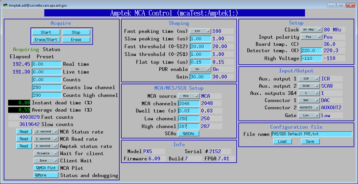
The following shows the MEDM screen for the Amptek control
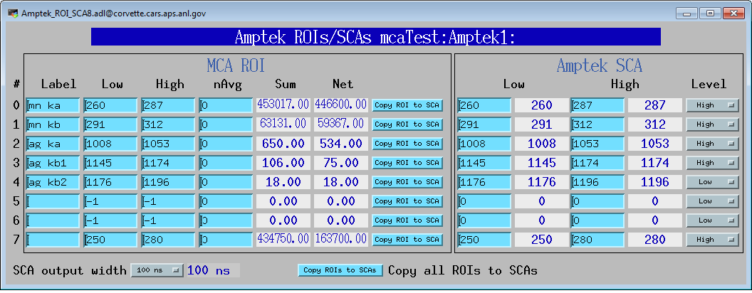
The following shows the MEDM screen for the Amptek single channel analyzer (SCA) configuration
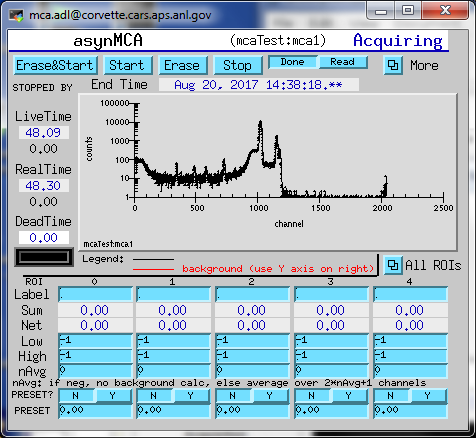
The following shows the MEDM screen for the MCA display with a PX5, XR-100CdTe detector and a Cd109 radioactive source
The mca/iocBoot/iocAmptek contains example startup scripts for the Amptek detectors.
The command to configure the Amptek driver is drvAmptekConfigure().
int drvAmptekConfigure(const char *portName, int interfaceType, const char *addressInfo, int directMode)
  The arguments are:
      portName:            # The name of the asyn port to be created
      interfaceType:       # The interface to use: 0=Ethernet, 1=USB, 2=RS-232
      addressInfo          # The device address information.
                           # For Ethernet this is the IP address of the module.
                           # For USB, this argument may be the serial number
                           #   or left blank for the default unit.
                           # RS-232 is not currently supported.
      directMode:          # Enable broadcast-less connection: 0=use broadcast,
                           #   1=skip broadcast
The driver currently has the following restrictions. These may be addressed in future releases.