pointGrey.adl
This is an EPICS areaDetector driver for cameras from Point Grey. These include IEEE 1394 Firewire DCAM, GigE, USB 2.0, and USB 3.0 cameras. The driver should work with any Point Grey camera. It has been tested on Firewire (Flea2), GigE (BlackFly, Flea3, Grasshopper3), and USB 3.0 (Grasshopper3) cameras. The driver has been tested on Windows and Linux with all 3 of these cameras. Note that Point Grey Firewire cameras can also be controlled by the generic areaDetector Windows Firewire driver and the areaDetector Linux Firewire driver, which work with Firewire cameras from any vendor. However, this Point Grey driver provides access to some vendor-specific features like strobe outputs that are not available in the generic drivers.
On Linux the Point Grey FlyCap2 SDK requires glibc version 2.14. This means it cannot be used on RHEL 6, but it can be used on RHEL 7, and Fedora 15 and higher. For USB 3.0 cameras kernel version 3.5.0 or higher is required. This means USB 3.0 cameras require Fedora 18 or higher, or RHEL 7.0 or higher.
This driver inherits from ADDriver. It implements many of the parameters in asynNDArrayDriver.h and in ADArrayDriver.h. It also implements a number of parameters that are specific to the Point Grey cameras. The pointGrey class documentation describes this class in detail.
The Point Grey cameras use the IIDC/DCAM model for controlling features like shutter time, white balance, frame sizes, shutter time, frame rates, etc. This model is used not only for the IEEE 1394 Firewire cameras, for which the IIDC/DCAM model was developed, but also for their USB and GigE cameras. The Point Grey driver thus has many similarities to the generic areaDetector Windows Firewire driver and the areaDetector Linux Firewire driver. The FlyCapture2 SDK abstracts this model to a certain extent, which facilitates writing a driver that works with all of the Point Grey cameras.
Point Grey frequently updates the available firmware for each camera to add features and fix bugs. However, they are not very good about putting the link to the latest firmware on their Web site. They claim this is because they only put the firmware on the Web site once it has been tested on all camera models in the camera family on which that firmware runs. In practice the firmware version listed on the Web site is often old and buggy. I have encouraged them to make the latest firmware more easily available. At present one must e-mail the support team (support@ptgrey.com) and ask them if newer firmware is available for a particular camera, and if so to provide access to it. They normally do this by sending a link to a Dropbox folder.
The DCAM specification defines standard video formats, and a set of video modes for each video format. Point Grey combines the video format and video mode into a single quantity they call VideoMode. The following table lists these standard video modes.
Video mode Format7 is special. It allows defining an ROI on the camera to read out. The pixel resolution with which the size and position of this ROI can be defined can be queried, and is not necessarily a single pixel. In Format 7 the frame rate settings do not apply, and there is a another setting called PixelFormat that controls the video format, e.g. Mono8, Mono16, RGB8, etc.
Most cameras only support a small subset of these standard modes. The EPICS record $(P)$(R)VideoMode is an mbbo record that only has choices for the video modes actually available on the specific camera in use. Since mbbo records only allow a maximum of 16 choices and there are 24 standard video modes, it is conceivable that all available videos modes would not be presented. In practice this is not a problem since no existing camera supports more than 16 video modes.
| Point Grey Video Modes | |
| Mode Number | Mode Description |
|---|---|
| 0 | 160x120 YUV444 |
| 1 | 320x240 YUV422 |
| 2 | 640x480 YUV411 |
| 3 | 640X480 YUV422 |
| 4 | 640x480 RGB |
| 5 | 640x480 Mono8 |
| 6 | 640x480 Mono16 |
| 7 | 800x600 YUV422 |
| 8 | 800x600 RGB |
| 9 | 800x600 Mono8 |
| 10 | 1024x768 YUV422 |
| 11 | 1024x768 RGB |
| 12 | 1024x768 Mono8 |
| 13 | 800x600 Mono16 |
| 14 | 1024x768 Mono16 |
| 15 | 1280x960 YUV422 |
| 16 | 1280x960 RGB |
| 17 | 1280x960 Mono8 |
| 18 | 1600x1200 YUV422 |
| 19 | 1600x1200 RGB |
| 20 | 1600x1200 Mono8 |
| 21 | 1280x960 Mono16 |
| 22 | 1600x1200 Mono16 |
| 23 | Format7 (user-defined) |
When the video mode is Format7 then there is an available selection of Format7 modes. These modes are not defined in the IIDC/DCAM standard, but are specific to each vendor and camera. Typically Format7 mode 0 is the entire chip unbinned, and mode 1 is often the entire chip with 2x2 binning. The supported Format7 modes are listed in the Point Grey Technical Reference Manual for each camera. The EPICS Format7Mode record is used to select the Format7 mode to use. This is an mbbo record and the enum choices are only those supported by the camera in use. The enum strings are of the form "Format7 mode # (NYxNY)", for example "0 (1920x1200)" or "1 (960x600)" for Format7 modes 0 and 1 respectively on a camera with 1920 x 1200 pixels.
When the video mode is Format7 then there is an available selection of PixelFormats. The available PixelFormats depend on the selected Format7 mode. Selection of a PixelFormat is done with the EPICS PixelFormat record. This is an mbbo record that only has choices that are valid for the currently selected Format7 mode. The enum values in this record are thus dynamic, and it is displayed in a separate GUI window that must be closed and re-opened when the Format7 mode changes in order to guarantee that it is displaying the currently valid PixelFormat choices.
The following tables lists the standard pixel formats for video mode Format7. Note that typically only a few of these pixel formats are supported on a particular camera with a specific Format7 mode.
| Point Grey Format7 Pixel Formats | |
| Pixel Format Number | Pixel Format Description |
|---|---|
| 0 | Mono8 |
| 1 | YUV411 |
| 2 | YUV422 |
| 3 | YUV444 |
| 4 | RGB8 |
| 5 | Mono16 |
| 6 | RGB16 |
| 7 | Mono16_Signed |
| 8 | RGB16_Signed |
| 9 | Raw8 |
| 10 | Raw16 |
| 11 | Mono12 |
| 12 | Raw12 |
| 13 | BGR |
| 14 | BGRU |
| 15 | BGR16 |
| 16 | BGRU16 |
| 17 | YUV422_JPEG |
The following tables lists the standard IIDC/DCAM frame rates for video modes other than Format7. Selecting a video mode (other than Format7) defines the choice of available standard frame rates. Selecting a standard frame rate actually defines a range of frame rates that are available, and the actual frame rate can be adjusted within this range with the FrameRate property. The FrameRate property is controlled with the EPICS FrameRateAbsVal or AcquirePeriod records.
Selection of a standard frame rate is done with the EPICS FrameRate record. This is an mbbo record that only has choices that are valid for the currently selected video mode. The enum values in this record are thus dynamic, and it is displayed in a separate GUI window that must be closed and re-opened when the video mode changes in order to guarantee that it is displaying the currently valid FrameRate choices. Note that not all frame rates are supported by the IIDC standard for every video mode, and even when a frame rate is supported by the standard it may not be implemented for a particular camera.
In Format 7 the frame rate settings do not apply, and the frame rate is controlled solely by the FrameRate property.
| Standard IIDC/DCAM Video Frame Rates | |
| Frame Rate Number | Frame Rate (Frames/second) |
|---|---|
| 0 | 1.875 |
| 1 | 3.75 |
| 2 | 7.5 |
| 3 | 15 |
| 4 | 30 |
| 5 | 60 |
| 6 | 120 |
| 7 | 240 |
The DCAM specification defines a number of standard features, which control things such as the brightness, white balance, shutter time, etc. For each feature the standard defines control in both device units (12-bit integers) and absolute units (floating point). For example shutter time may support absolute seconds, as well as device units. A feature may or may not be supported on a particular camera. If it is supported it may or may not permit control in absolute units. Each feature may support both manual control and automatic control (e.g. automatic gain control).
Point Grey supports 18 of these DCAM features, which they call Properties.
| Point Grey Camera Properties | ||
| Property Number | EPICS Record Base Name | Point Grey PropertyType enum |
|---|---|---|
| 0 | Brightness | BRIGHTNESS |
| 1 | AutoExposure | AUTO_EXPOSURE |
| 2 | Sharpness | SHARPNESS |
| 3 | WhiteBalance | WHITE_BALANCE |
| 4 | Hue | HUE |
| 5 | Saturation = | SATURATION |
| 6 | Gamma | GAMMA |
| 7 | Iris | IRIS |
| 8 | Focus | FOCUS |
| 9 | Zoom | ZOOM |
| 10 | Pan | PAN |
| 11 | Tilt | TILT |
| 12 | Shutter | SHUTTER |
| 13 | Gain | GAIN |
| 14 | TriggerMode | TRIGGER_MODE |
| 15 | TriggerDelay | TRIGGER_DELAY |
| 16 | FrameRate | FRAME_RATE |
| 17 | Temperature | TEMPERATURE |
Point Grey supports 4 properties that are specific to GigE cameras.
| Point Grey Camera Properties | ||
| Property Number | EPICS Record Base Name | Point Grey PropertyType enum |
|---|---|---|
| 0 | Heeartbeat | HEARTBEAT |
| 1 | HeartbeatTimeout | HEARTBEAT_TIMEOUT |
| 2 | PacketSize | PACKET_SIZE |
| 3 | PacketDelay | PACKET_DELAY |
The following table describes how the Point Grey driver implements some of the standard driver parameters.
| Implementation of Parameters in asynNDArrayDriver.h and ADDriver.h, and EPICS Record Definitions in ADBase.template and NDFile.template | ||
| Parameter index variable | EPICS record name | Description |
|---|---|---|
| ADTriggerMode | $(P)$(R)TriggerMode |
The choices for the Point Grey are:
|
| ADTemperatureActual | $(P)$(R)TemperatureActual | The readback of the temperature. |
| ADNumImages | $(P)$(R)NumImages | Controls the number of images to acquire. When TriggerMode=Internal this is handled in software. When TriggerMode=Multi-shot it is handled in the camera firmware. |
| ADNumExposures | $(P)$(R)NumExposures | Controls the number of exposures per image when TriggerMode="Multi-exposure" or "Multi-exposure bulb". |
| ADAcquireTime | $(P)$(R)AcquireTime | Controls the acquisition time per image. This is converted into the ShutterAbsVal control of the SHUTTER property. ShutterAbsVal = AcquireTime*1000., because SHUTTER units are ms. |
| ADAcquirePeriod | $(P)$(R)AcquirePeriod | Controls the period between images. This is converted into the FrameRateAbsVal control of the FRAME_RATE property. FrameRateAbsVal = 1./AcquirePeriod. |
| ADGain | $(P)$(R)Gain | Controls the analog gain on the camera. This is converted into the GainAbsVal control of the GAIN property. The units are dB. |
The Point Grey driver implements the following parameters in addition to those in asynNDArrayDriver.h and ADDriver.h. The database file is pointGrey.template for all records except the property records, which are in pointGreyProperty.template.
| Parameter Definitions in firewireWinDCAM.cpp and EPICS Record Definitions | ||||||
| Parameter index variable | asyn interface | Access | Description | drvInfo string | EPICS record name | EPICS record type |
|---|---|---|---|---|---|---|
| Video mode parameters | ||||||
| PGVideoMode | asynInt32 | r/w | The video mode. All possible values are listed in the Video modes section above. The actual enum choices for this record will only include the video modes supported by the camera in use. | PG_VIDEO_MODE |
$(P)$(R)VideoMode $(P)$(R)VideoMode_RBV |
mbbo
mbbi |
| PGFormat7Mode | asynInt32 | r/w | The Format7 mode when the camera is in VideoMode=Format7. This is discussed in the Format7 modes section above. The actual enum choices for this record will only include the Format7 modes supported by the camera in use. | PG_FORMAT7_MODE |
$(P)$(R)Format7Mode $(P)$(R)Format7Mode_RBV |
mbbo
mbbi |
| PGPixelFormat | asynInt32 | r/w | The pixel format when the camera is in VideoMode=Format7. This is discussed in the Pixel formats section above. The actual enum choices for this record will only include the pixel formats supported by the camera in use for the Format7Mode currently selected. | PG_PIXEL_FORMAT |
$(P)$(R)PixelFormat $(P)$(R)PixelFormat_RBV |
mbbo
mbbi |
| PGConvertPixelFormat | asynInt32 | r/w |
The driver allows converting the pixel format from the camera to another pixel format.
The pixel formats from the camera that can be converted are:
|
PG_CONVERT_PIXEL_FORMAT |
$(P)$(R)ConvertPixelFormat $(P)$(R)ConvertPixelFormat_RBV |
mbbo
mbbi |
| PGFrameRate | asynInt32 | r/w | The frame rate choice when the VideoMode is not Format7. This is discussed in the Frame rates section above. The actual enum choices for this record will only include the frame rates supported by the camera in use for the VideoMode currently selected. | PG_FRAME_RATE |
$(P)$(R)FrameRate $(P)$(R)FrameRate_RBV |
mbbo
mbbi |
| BinningMode | asynInt32 | r/w | The binning mode for GigE cameras. The allowed values are camera-specific. | PG_BINNING_MODE |
$(P)$(R)BinningMode $(P)$(R)BinningMode_RBV |
mbbo
mbbi |
|
Property parameters These parameters apply to each of the 18 Point Grey properties discussed in the Properties section above. The $(PROPERTY) macro in this table is the EPICS record base name listed in that section. These records are defined in pointGreyProperty.template. |
||||||
| PGPropertyAvail | asynInt32 | r/o | A flag indicating if the property is available. | PG_PROP_AVAIL | $(P)$(R)$(PROPERTY)Avail | bi |
| PGPropertyOnOffAvail | asynInt32 | r/o | A flag indicating if the property supports turning on and off. | PG_PROP_ON_OFF_AVAIL | $(P)$(R)$(PROPERTY)OnOffAvail | bi |
| PGPropertyOnOff | asynInt32 | r/w | Controls whether the property is on or off. | PG_PROP_ON_OFF |
$(P)$(R)$(PROPERTY)OnOff
$(P)$(R)$(PROPERTY)OnOff_RBV |
bo
bi |
| PGPropertyOnePushAvail | asynInt32 | r/o | A flag indicating if the property supports setting once (called One Push). This is typically used for setting things like the gain or shutter time automatically once. | PG_PROP_ONE_PUSH_AVAIL | $(P)$(R)$(PROPERTY)OnePushAvail | bi |
| PGPropertyOnePush | asynInt32 | r/w | Processing this record causes a one-push setting of the property. | PG_PROP_ONE_PUSH | $(P)$(R)$(PROPERTY)OnePush | bo |
| PGPropertyAbsAvail | asynInt32 | r/o | A flag indicating if the property supports absolute (floating point) control. | PG_PROP_ABS_AVAIL | $(P)$(R)$(PROPERTY)AbsAvail | bi |
| PGPropertyAutoAvail | asynInt32 | r/o | A flag indicating if the property supports automatic control. | PG_PROP_AUTO_AVAIL | $(P)$(R)$(PROPERTY)AutoAvail | bi |
| PGPropertyManAvail | asynInt32 | r/o | A flag indicating if the property supports manual control. | PG_PROP_MAN_AVAIL | $(P)$(R)$(PROPERTY)ManAvail | bi |
| PGPropertyAutoMode | asynInt32 | r/w | Controls whether the property is manually controlled or automatically controlled. | PG_PROP_AUTO_MODE |
$(P)$(R)$(PROPERTY)AutoMode
$(P)$(R)$(PROPERTY)AutoMode_RBV |
bo
bi |
| PGPropertyAbsAvail | asynInt32 | r/o | A flag indicating if the property supports absolute (floating point) control. | PG_PROP_ABS_AVAIL | $(P)$(R)$(PROPERTY)AbsAvail | bi |
| PGPropertyAbsMode | asynInt32 | r/w | Controls whether the property is controlled in integer device units or floating point absolute units. | PG_PROP_ABS_MODE |
$(P)$(R)$(PROPERTY)AbsMode
$(P)$(R)$(PROPERTY)AbsMode_RBV |
bo
bi |
| PGPropertyValue | asynInt32 | r/w | The value of the property in integer device units. This controls the ValueA field of the property, which is the only integer field used for all properties except WHITE_BALANCE. | PG_PROP_VAL |
$(P)$(R)$(PROPERTY)Val
$(P)$(R)$(PROPERTY)Val_RBV |
ao
ai |
| PGPropertyValueB | asynInt32 | r/w | The value of the property in integer device units. This controls the ValueB field of the property, which is only used to control the Blue value of WHITE_BALANCE. | PG_PROP_VAL_B |
$(P)$(R)$(PROPERTY)ValB
$(P)$(R)$(PROPERTY)ValB_RBV |
ao
ai |
| PGPropertyValueMin | asynInt32 | r/o | The minimum value of the property in device units. This is used to control the LOPR and DRVL fields of the $(P)$(R)$(PROPERTY)Val record. | PG_PROP_VAL_MIN | $(P)$(R)$(PROPERTY)ValMin | ai |
| PGPropertyValueMax | asynInt32 | r/o | The maximum value of the property in device units. This is used to control the HOPR and DRVH fields of the $(P)$(R)$(PROPERTY)Val record. | PG_PROP_VAL_MAX | $(P)$(R)$(PROPERTY)ValMax | ai |
| PGPropertyValueAbs | asynFloat64 | r/w | The value of the property in floating point absolute units. | PG_PROP_VAL_ABS |
$(P)$(R)$(PROPERTY)ValAbs
$(P)$(R)$(PROPERTY)ValAbs_RBV |
ao
ai |
| PGPropertyValueAbsMin | asynFloat64 | r/o | The minimum value of the property in absolute units. This is used to control the LOPR and DRVL fields of the $(P)$(R)$(PROPERTY)ValAbs record. | PG_PROP_VAL_ABS_MIN | $(P)$(R)$(PROPERTY)ValAbsMin | ai |
| PGPropertyValueAbsMax | asynFloat64 | r/o | The maximum value of the property in absolute units. This is used to control the HOPR and DRVH fields of the $(P)$(R)$(PROPERTY)ValAbs record. | PG_PROP_VAL_ABS_MAX | $(P)$(R)$(PROPERTY)ValAbsMax | ai |
|
GigE Property parameters These parameters apply to each of the 4 Point Grey GigE properties discussed in the GigE Properties section above. The $(PROPERTY) macro in this table is the EPICS record base name listed in that section. These records are defined in pointGreyProperty.template. |
||||||
| PGPropertyValue | asynInt32 | r/w | The value of the property in integer device units. This controls the ValueA field of the property, which is the only integer field used for all properties except WHITE_BALANCE. | PG_PROP_VAL |
$(P)$(R)$(PROPERTY)Val
$(P)$(R)$(PROPERTY)Val_RBV |
ao
ai |
| PGPropertyValueMin | asynInt32 | r/o | The minimum value of the property in device units. This is used to control the LOPR and DRVL fields of the $(P)$(R)$(PROPERTY)Val record. | PG_PROP_VAL_MIN | $(P)$(R)$(PROPERTY)ValMin | ai |
| PGPropertyValueMax | asynInt32 | r/o | The maximum value of the property in device units. This is used to control the HOPR and DRVH fields of the $(P)$(R)$(PROPERTY)Val record. | PG_PROP_VAL_MAX | $(P)$(R)$(PROPERTY)ValMax | ai |
| Trigger parameters | ||||||
| PGTriggerSource | asynInt32 | r/w | The trigger source signal. Choices are "GPIO_0", GPIO_1","GPIO_2", and "GPIO_3", which selects one of 4 GPIO pins on the camera. However, not all choices may be available on a specific camera, and the enum choices will only be the trigger sources actually supported on the camera in use. | PG_TRIGGER_SOURCE |
$(P)$(R)TriggerSource
$(P)$(R)TriggerSource_RBV |
mbbo
mbbi |
| PGTriggerPolarity | asynInt32 | r/w | The trigger polarity. Choices are "Low", and "High". | PG_TRIGGER_POLARITY |
$(P)$(R)TriggerPolarity
$(P)$(R)TriggerPolarity_RBV |
bo
bi |
| PGSoftwareTrigger | asynInt32 | r/w | Processing this record causes the driver to issue a software trigger. | PG_SOFTWARE_TRIGGER | $(P)$(R)SoftwareTrigger | bo |
| PGSkipFrames | asynInt32 | r/w | The number of frames to skip when TriggerMode="Skip frames". | PG_SKIP_FRAMES |
$(P)$(R)SkipFrames
$(P)$(R)SkipFrames_RBV |
longout
longin |
| Strobe parameters | ||||||
| PGStrobeSource | asynInt32 | r/w | The strobe output signal. Choices are "GPIO_0", GPIO_1","GPIO_2", and "GPIO_3", which selects one of 4 GPIO pins on the camera. However, not all choices may be available on a specific camera, and the enum choices will only be the strobe sources actually supported on the camera in use. | PG_STROBE_SOURCE |
$(P)$(R)StrobeSource
$(P)$(R)StrobeSource_RBV |
mbbo
mbbi |
| PGStrobeEnable | asynInt32 | r/w | Enables the strobe output. Choices are "Disable", and "Enable". | PG_STROBE_ENABLE |
$(P)$(R)StrobeEnable
$(P)$(R)StrobeEnable_RBV |
bo
bi |
| PGStrobePolarity | asynInt32 | r/w | The strobe polarity. Choices are "Low", and "High". | PG_STROBE_POLARITY |
$(P)$(R)StrobePolarity
$(P)$(R)StrobePolarity_RBV |
bo
bi |
| PGStrobeDelay | asynFloat64 | r/w | The delay of the strobe signal relative to the start of acquisition. | PG_STROBE_DELAY |
$(P)$(R)StrobeDelay
$(P)$(R)StrobeDelay_RBV |
ao
ai |
| PGStrobeDuration | asynFloat64 | r/w | The duration of the strobe signal. If zero then the strobe output is asserted during the image aquisition time. | PG_STROBE_DURATION |
$(P)$(R)StrobeDuration
$(P)$(R)StrobeDuration_RBV |
ao
ai |
| Bandwidth control parameters | ||||||
| PGMaxPacketSize | asynInt32 | r/o | The maximum packet size. This depends on the current acquisition settings for Firewire and USB cameras. For GigE cameras this is determined by calling DiscoverGigEPacketSize at startup, which should return the maximum Ethernet packet size supported between the camera and the IOC. However, this sometimes returns 9000 (jumbo packets) when jumbo packets are not in fact supported. In this case the user should manually set PacketSize to 1440 or image acquisition will fail. | PG_MAX_PACKET_SIZE | $(P)$(R)MaxPacketSize | longin |
| PGPacketSize | asynInt32 | r/w | The packet size to use. This is used to control the maximum bandwidth, and hence maximum frame rate, on Firewire and USB cameras. For GigE cameras it should be set to the largest packet size supported on the Ethernet connection between the camera and IOC. It should be set to 1440 for connections that do not support jumbo packets, and as large as 9000 for connections that do support jumbo packets. If PacketSize is set to 0 then the driver will use the current value of MaxPacketSize. | PG_PACKET_SIZE |
$(P)$(R)PacketSize
$(P)$(R)PacketSize_RBV |
ao
ai |
| PGPacketSizeActual | asynInt32 | r/o | The actual packet size being used. | PG_PACKET_SIZE_ACTUAL | $(P)$(R)PacketSizeActual | longin |
| PGPacketDelay | asynInt32 | r/w | The packet delay to use in microseconds. This is used to control the maximum bandwidth, and hence maximum frame rate, on GigE cameras. It is not used for Firewire or USB cameras. The default is 400 microseconds. If the number of CorruptFrames is large then this can be increased, for example to 1000. This will reduce the maximum frame rate but can significantly reduce the number of CorruptFrames. | PG_PACKET_DELAY |
$(P)$(R)PacketDelay
$(P)$(R)PacketDelay_RBV |
longout
longin |
| PGPacketDelayActual | asynInt32 | r/o | The actual packet delay being used. | PG_PACKET_DELAY_ACTUAL | $(P)$(R)PacketDelayActual | longin |
| PGBandwidth | asynFloat64 | r/o | The calculated bandidth in MB/s. This is computed from the image size and the frame rate. | PG_BANDWIDTH | $(P)$(R)Bandwidth | ai |
| Timestamp parameters | ||||||
| PGTimeStampMode | asynInt32 | r/w |
The timestamp mode. Controls the value of the NDArray,.timeStamp value. Choices
are:
|
PG_TIME_STAMP_MODE |
$(P)$(R)TimeStampMode
$(P)$(R)TimeStampMode_RBV |
mbbo
mbbi |
| Camera statistics | ||||||
| PGCorruptFrames | asynInt32 | r/o | The number of corrupt frames. The Point Grey SDK resets this to 0 each time acquisition is started. | PG_CORRUPT_FRAMES | $(P)$(R)CorruptFrames_RBV | longin |
| PGDroppedFrames | asynInt32 | r/o | The number of dropped frames. The Point Grey SDK resets this to 0 each time acquisition is started. | PG_DROPPED_FRAMES | $(P)$(R)DroppedFrames_RBV | longin |
| PGDriverDropped | asynInt32 | r/o | The number of frames dropped by the driver. The Point Grey SDK resets this to 0 each time acquisition is started. | PG_DRIVER_DROPPED | $(P)$(R)DriverDropped_RBV | longin |
| PGTransmitFailed | asynInt32 | r/o | The number of time transmission failed. The Point Grey SDK resets this to 0 each time acquisition is started. | PG_TRANSMIT_FAILED | $(P)$(R)TransmitFailed_RBV | longin |
The Point Grey driver is created with the pointGreyConfig command, either from C/C++ or from the EPICS IOC shell.
pointGreyConfig(const char *portName, const char* cameraId, int traceMask, int memoryChannel,
              int maxBuffers, size_t maxMemory,
              int priority, int stackSize)
The cameraId parameter can either be an index of the camera in the list of available cameras (e.g. 0 if there is only a single Point Grey camera available) or the serial number of the camera to use. For additional details on the meaning of the parameters to this function refer to the detailed documentation on the pointGreyConfigConfig function in the pointGrey.cpp documentation and in the documentation for the constructor for the pointGrey class.
The traceMask can be set to a value > 1 to enable asynTrace debugging during initialization, before the value can be set from the IOC shell or via the asynRecord. Set this to 0x21 to enable ASYN_TRACE_WARNING, which will trace all calls to the Point Grey FlyCap2 library.
The memoryChannel can be set to a value > 0 to load the initial camera parameters from non-volatile memory in the camera. Setting memoryChannel to N loads from memoryChannel N-1, i.e. 1 loads memory channel 0. There is currently a problem with Linux and for BlackFly GigE cameras. If the IOC is run a second time after it has been used to acquire any images the driver loses communication with the camera. The problem appears to be that there is a corrupt setting in the camera, which causes it to malfunction the next time the program is run. Setting memoryChannel 1 will work around this problem by replacing the settings in the camera with a default set. Since the EPICS IOC sets nearly all the camera settings to save/restore values at startup anyway, this is not a serious limitation.
There an example IOC boot directory and startup script (iocBoot/iocPointGrey/st.cmd) provided with areaDetector.
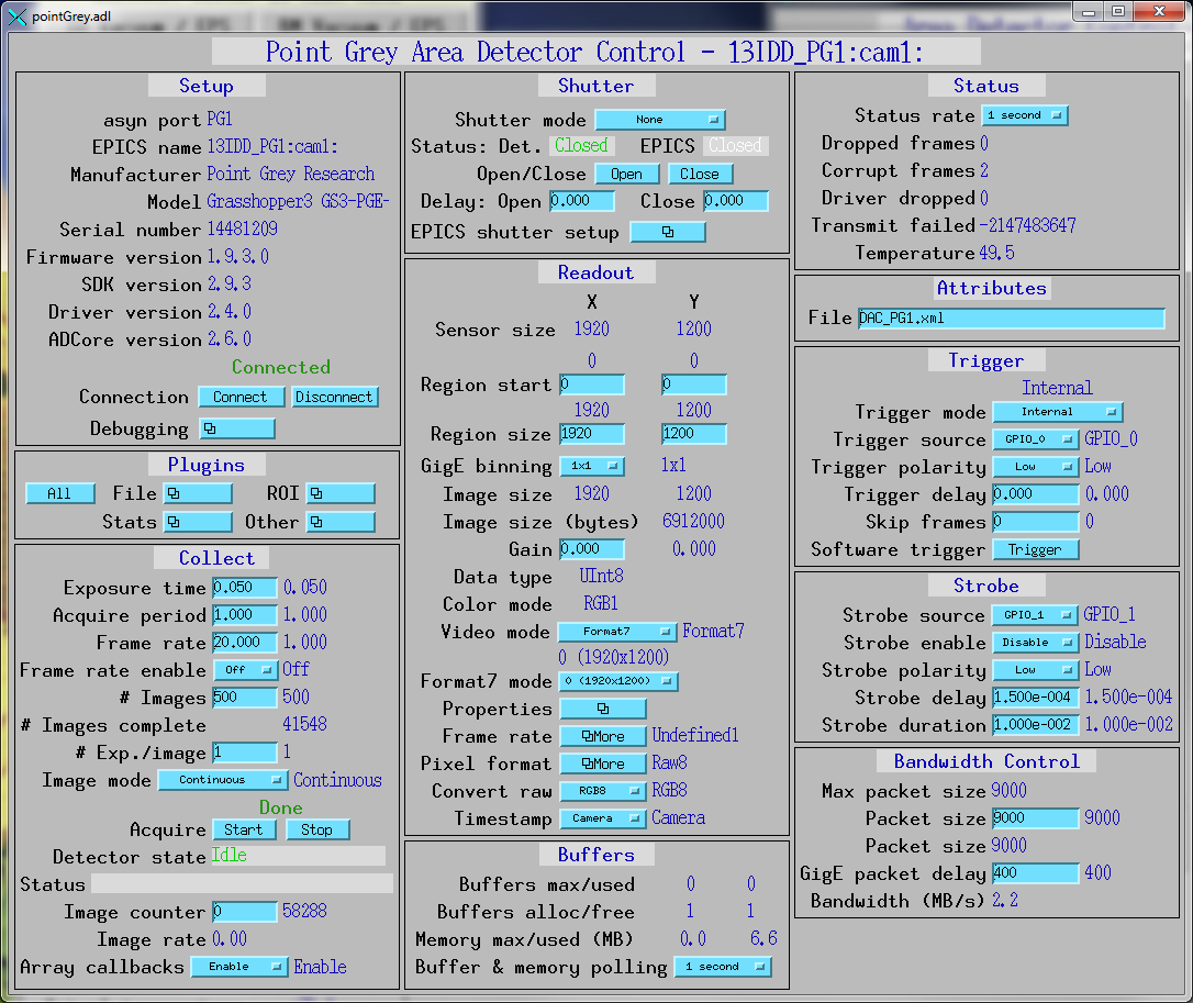
The following show the MEDM screens that are used to control the Point Grey cameras.
pointGrey.adl is the main screen used to control Point Grey cameras.
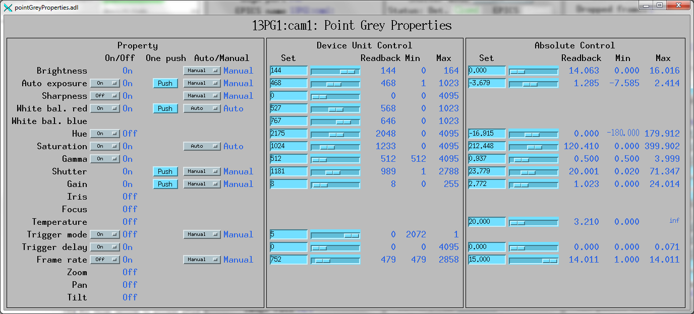
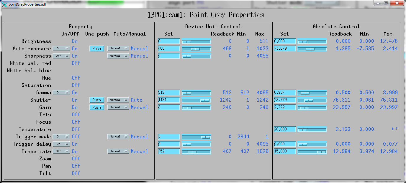
pointGreyProperties.adl is the screen used to control the properties
of Point Grey cameras. Note that some of these properties, such as Shutter, FrameRate,
and Gain can also be controlled by standard areaDetector records, like AcquireTime,
AcquirePeriod, and Gain. The widgets on the medm screen are hidden if the corresponding
feature is not available.
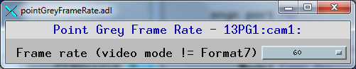
pointGreyFrameRate.adl is the screen used to control the frame rate
in standard video modes. This is a separate screen because the valid enum strings
for the Framerate record can change when the standard video mode is changed. When
that is changed it is necessary to close this screen and re-open it in order for
the new menus to be displayed. This is a limitation of the EPICS Channel Access
which does not send monitor events for changes in enum fields. Note that the readback
of the FrameRate on the main pointGrey.adl screen can also be incorrect, so it may
be necessary to close and re-open that main screen as well.
pointGreyPixelFormat.adl is the screen used to control the pixel format
in Format7 mode. This is a separate screen because the valid enum strings for the
PixelFormat can change when the Format7 mode is changed. When that is changed it
is necessary to close this screen and re-open it in order for the new menus to be
displayed. This is a limitation of the EPICS Channel Access which does not send
monitor events for changes in enum fields. Note that the readback of the PixelFormat
on the main pointGrey.adl screen can also be incorrect, so it may be necessary to
close and re-open that main screen as well.